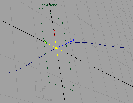
Use the Plane tool to create a reference plane which you can use as input to tools requiring a plane, or as the construction plane.
Create a reference or construction plane
- Choose Construction > Plane
 .
. Five buttons appear at the bottom of the view window. Each allows you to create a different type of construction plane. The five types are:
- View
- This is a 1-point construction plane where you specify the center point of the plane. The plane is oriented so that the Z-axis is parallel to the view vector. You can also snap the point to any geometry.
- Slice
- This is a new type of plane where you specify 2 points. The third point is placed at the eye position so that you are looking at the plane from the edge. This type of plane is useful for defining cross sections.
- 3 Pt
- This is the regular 3-point construction plane where you completely define the plane by inputting three points.
- Geom
- This lets you snap the center point of the plane to geometry so that the Z-axis is oriented along the surface normal or curve tangent.
- World
- This is also a 1-point plane. You specify the center point and the three axes are oriented along the world axes. You can snap the point to any geometry. Note: View, Geom, and World planes have manipulators that you can use to tweak the orientation of the plane.
- Select the type of plane you want to create.
(The on-screen buttons are optional. You can ignore them by clicking in the display—the selection from the option window will be used instead.)
- Click to place one, two, or three points, according to the instructions on the prompt line. You can also type the 3D coordinates for a point.
- Adjust the plane by moving the point(s), or using the manipulator (if available), to move, rotate, and size the plane.
- To make this plane a reference plane, and go on to create another plane, click Next Plane.
To make this plane the construction plane, click Set Construction Plane.
Note:There can only be one construction plane in a scene. If you create a construction plane and there is already a construction plane in the scene, the existing construction plane will become a reference plane.
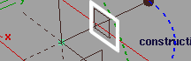
How to use the plane manipulator
Click a handle to select it (the handle becomes white), then either:
- Drag the handle to move/rotate/scale the plane. (See Interactive manipulation.)
- Type exact values on the keyboard.
- Click the geometry or the grid, while using a snap mode, to snap the axes of the manipulator to a specific position or orientation.
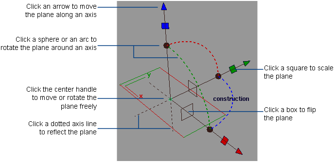
Interactive manipulation
- Drag an arrow handle to move the plane along an axis.

- Drag a dotted arc to rotate the plane around the axis with the same color (the axis perpendicular to the arc).

- Drag a square handle to scale the plane along the axis that has the same color as the square.
- Drag the center handle to move the plane freely.
- Click one of the rectangular boxes to flip the plane to one of the two perpendicular orientations.
- Click a dotted axis line to reflect the plane across the X, Y, or Z axes.
- Use Edit > Undo
 to undo changes to the manipulator.
Edit a reference or construction plane
- Pick the plane.
- Choose Construction > Plane .
The points and manipulator (if applicable to this type of plane) appear.
Note:You can also select the Plane tool first, then select the plane you want to edit.
- Adjust the plane by dragging the point(s), or using the manipulator. Tip:
Open the Information window (Windows > Information > Information Window
 ) to see detailed information as you manipulate the plane.
 - To make the plane a reference plane and go on to create another plane, click Next Plane.
To make this plane the construction plane, click Set Construction Plane.
Note:There can only be one construction plane in a scene. If you create a construction plane and there is already a construction plane in the scene, the existing construction plane will become a reference plane.
Choose a construction plane
- To toggle between a construction plane and the world space coordinate system, choose Construction > Toggle Construction Plane
 .
. - To set a construction plane, pick a reference plane, then choose Construction > Set Construction Plane .
Hide or show reference/construction planes
Delete a reference/construction plane
- Pick only the reference/construction plane.
- Press the
 key, or choose Delete > Delete Active
  from the menus.
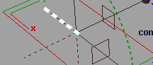
Snap to the intersection of a curve and a plane
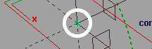
You can easily snap to a curve that intersects a construction plane, and position the snap point either anywhere along the curve, or precisely at the point where the curve and plane intersect.
If True Intersections is checked in Curve Snap Options, and you drag the snap point close to the construction plane, a yellow cross appears on the plane indicating that the snap point is precisely at the intersection point.