Tube flange enables you to define exactly where the tube starts. This is important for aesthetic reasons. Fillet flange enables you to control exactly the widest dimension of the fillet. This is important when creating cut lines that must have a specific gap distance.
These tools were designed to help you finish edges of surface models. Usually this is time consuming work that involves creating a fillet and a flange to finish the edge.
The rolled edge tool family enables you to create both the flange and the surface fillet with a single tool. This makes the edge finishing more efficient, and also makes maintaining the construction history of the complete surface set that defines the edge finish easier to accomplish.
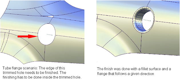
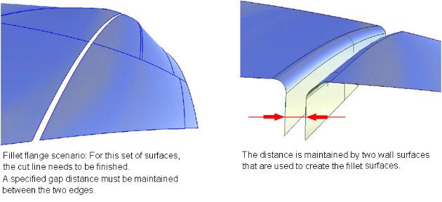
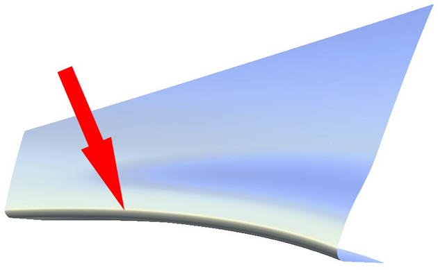
These two examples identify the two main cases for finishing surface edges. For the first case, there is a pre-defined contact line where the edge finish (consisting of a fillet and flange) needs to be added.
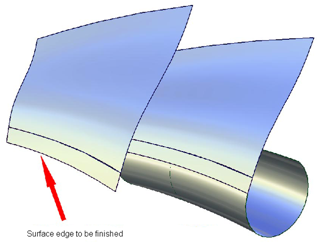
For the second case, a pre-defined silhouette line controls the creation of the fillet.
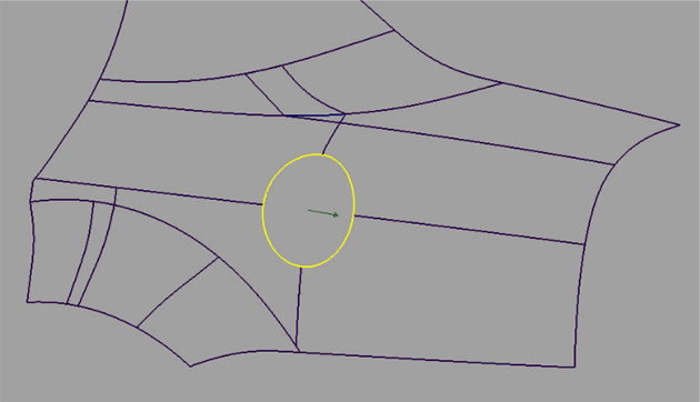
Pick edge curves for the Tube flange and Fillet flange tools
- Select one part of the edge to be selected.
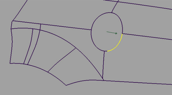
- Click-drag a pick box over the rest of the edges to be selected.
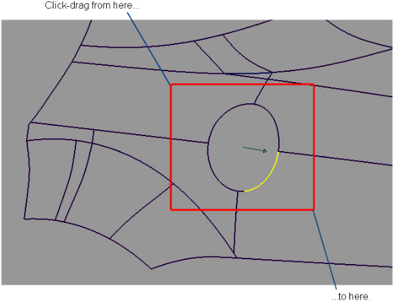
The curves forming the edge are selected.
After the edge is selected, you can select vectors to define the flange when the parting line method is used.
Create a tube flange finish
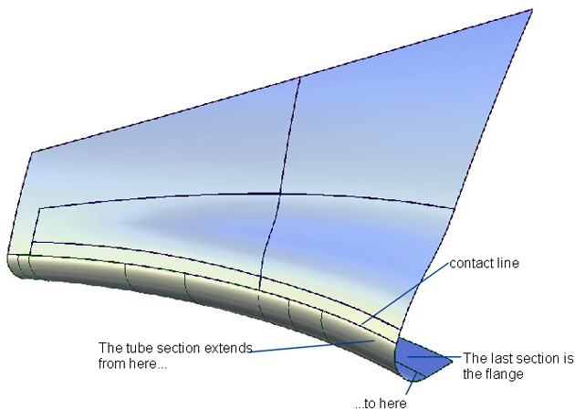
The Tube flange tool provides a solution for an edge finish where the focus is on the contact line. The contact line defines where the tube touches the main surface. It is important for aesthetic reasons to control the line where a highlight is changing. To do this, the Tube flange tool ensures that the new tube is added at the selected geometry.
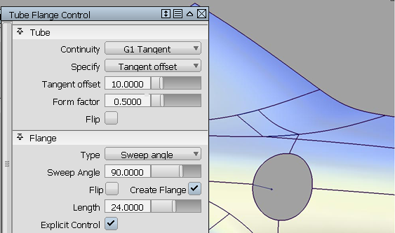
To create a tube
The Tube flange tool creates a tube touching the selected geometry (curves-on-surface, iso-parametric lines, or surface edges).
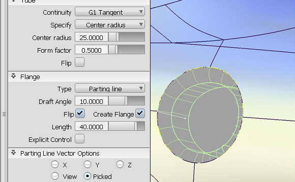
The tube has parameters that can be modified in the option window.
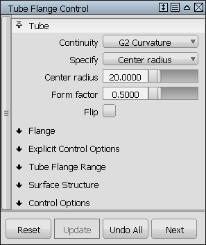
If you create a tube with G1 Tangent continuity, the tube is created with 360 degree sections. It will be trimmed to an appropriate section when creating the flange.
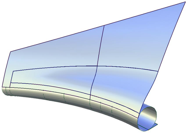
If you create a tube with G2 Curvature continuity, the tube will lose the 360 degree section, and be created between the contact line and the flange.
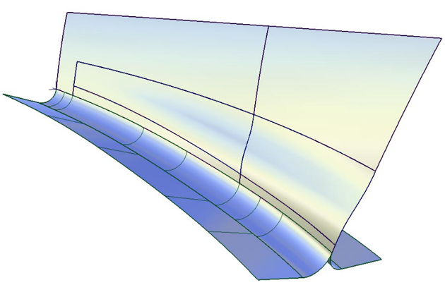
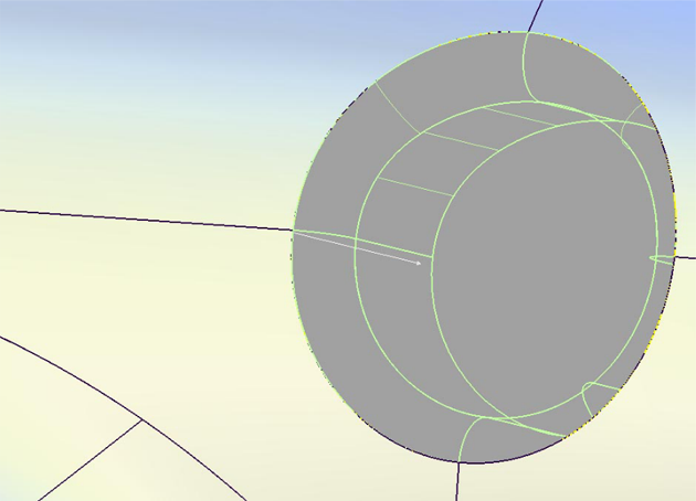
The image below shows a model with a tube and flange on both sides of the surface. Using the Flip checkbox in the control window (or blue arrow manipulator), you can specify on which side the tube will be built. A similar checkbox is available to control the direction of the flange if the tube is constructed on an interior isoparametric curve or a curve-on-surface. For tubes built on edges, the orientation of the flange is unique, and cannot be flipped.
To create a flange
- Sweep Angle
- Parting Line
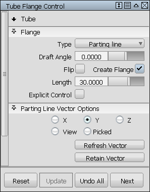
Based on a vector (selected by clicking it with the left mouse button, or specified through the option window), the tool analyzes the parting line and creates a linear extension called a flange.
There are two methods to calculate the flange at the end of the tube section. They are:
Detailed workflow
- Choose Surfaces > Rolled Edge > Tube Flange

- Select the geometry requiring an edge finish. Keep in mind that you can drag a pick box over the surface curves to be selected, or turn on Chain Select under the Control Options to select tangent continuous curves all at once. Clicking the geometry again de-selects it.
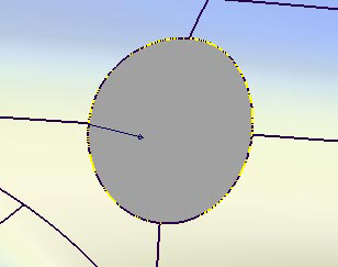
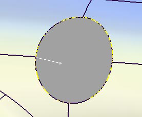
- With the Flange type set to Parting line, the vector defining the flange direction must be selected using the left mouse button. When selected, the vector turns white. The vector can also be specified through the Parting Line Vector Options.
- Click the Update button in the lower right section of the window.
- If the flange is not needed, make sure the Create Flange box is not checked.
- The Surface Structure section of the control window provides options to modify the span placement of the generated geometry. Setting Surface Type to Single surface creates a single tube and flange surface, otherwise the tube and flange are split at curve boundaries, which also include surface boundaries, since a curve cannot span more than one surface. This may provide you with better results, in terms of multi-span geometry. See the section Troubleshooting trimmed surfaces for more information.
Create a fillet flange finish
Use this tool to control the silhouette line of an edge finish.
When creating cut lines on a model, there is usually a certain predefined distance of the cut. To maintain this distance, the Fillet flange tool first creates a wall. This wall controls the appearance of the fillet and can be used to define the distance between two fillet flanges to create a cut line. This imaginary wall is used to help define the silhouette of the edge finish.
To create a fillet
- Depending on the Type chosen in the control window, one of two methods is used to create the wall at the selected geometry (either curves-on-surface, iso-parametric lines, or surface edges):
- Draft: the wall is a draft surface based on a pull direction vector. The vector can be selected by clicking it with the
 (while selected, the vector is blue) or specified through the Draft Vector Options.
 - Normal: the wall is a flange based on the surface normal of the selected geometry.
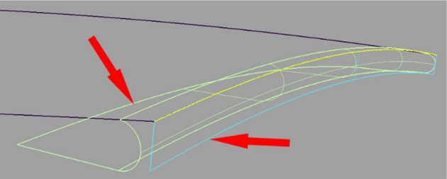
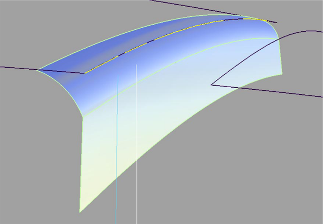
The wall is a temporary surface (shown in blue above) that is used to create the fillet surface . You can see it by turning on Show Wall in the Control Options. After you have finished constructing the fillet flange and exit the tool, the wall becomes invisible.
Now that you’ve got the wall in the right place, you need to create the fillet.
- Draft: the wall is a draft surface based on a pull direction vector. The vector can be selected by clicking it with the
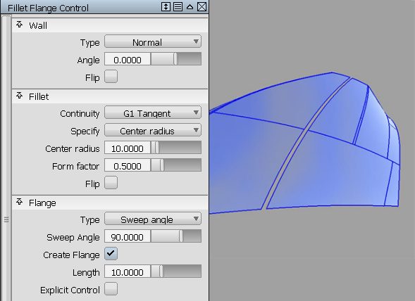
- The tool creates a fillet between the wall and the selected surfaces. The fillet can be tangent or curvature continuous with the input surface(s).
- Next, you create the flange.
At the end of the fillet, the tool creates a linear extension called a flange. The tool uses the same method as described in the section for the Tube tool.
Detailed workflow
- Choose Surfaces > Rolled Edge > Fillet Flange
- Select the geometry on which you need to finish the edge. Keep in mind that you can drag a pick box over the surface curves to be selected, or turn on Chain Select under the Control Options to select tangent continuous curves all at once. Clicking the geometry again de-selects it.
- Using the Draft option to create the wall, a vector for the draft direction has to be selected. The vector turns white when selected. You can also specify the vector through the Draft Vector Options.
- If you choose the parting line option, you must select a second vector by
 -picking it, if the Draft vector is active. This vector turns white. You can also specify the vector through the Parting Line Vector Options
 The variable parameter (radius, flange angle, or flange length — as specified by Variable in the control window) is controlled using a set of manipulators in the modeling window. Only one of the parameters can be varied: the other two are held constant.
See How to use the manipulators for more details.
- If you don’t need a flange at the end of the fillet, click the Create Flange check box to turn it off.
- Use the Flip checkbox in the control window (or blue arrow manipulator) to switch sides of the surface for building the wall, and thus, the fillet.
-
The Surface Structure section of the control window provides options to modify the span placement of the generated geometry. Setting Surface Type to Single surface creates a single fillet surface, otherwise the fillet is split at curve boundaries, which also include surface boundaries, since a curve cannot span more than one surface. This may provide you with better results, in terms of multi-span geometry.
Note:If Surface Type is set to Multiple surfaces, the curves-on-surface created at the edges of the fillets (visible when Auto Trim is off) are segmented to correspond to the multiple fillet surface boundaries. To create the curves-on-surface as a single piece (for each surface), set Surface Type to Single surface
How to use the manipulators
Each manipulator consists of two handles — the rail slider and the value handle — only one of which can be active at a given time. The active handle is shown in white. The rail slider, a "ball" sliding along the rail, indicates the position on the rail where the value applies. The value handle, an approximate cross section of the future surface, controls the value of the parameter at this point.
The value of the active handle is shown on the prompt line.
For all of the following operations, use the ![]() , unless stated otherwise.
, unless stated otherwise.
- To activate a handle, click on it.
- To de-activate the currently active handle and switch back to the picking mode, click anywhere on the screen (without dragging the mouse).
- To add a new manipulator, -click on the desired point on the rail.
- To move a manipulator, drag the slider ball using the . Alternatively, activate the slider ball and type in the position (in the range from 0 to 1) along the rail.
- To adjust the parameter value, click and drag the value handle. Once the handle is active, the mouse can be dragged anywhere on the screen. Alternatively, activate the handle and type in the value in current units.
- To delete a manipulator, -right click on it.
- If a single manipulator is used, the parameter is constant, and its value can also be adjusted in the control box. As soon as another manipulator is added, the value in the control box is grayed out.
Even after you have finished using the tool, you can rework the result by using Object Edit > Query Edit ![]() and clicking on the constructed surface with the
and clicking on the constructed surface with the ![]() . This re-opens the tool window with the settings for this construction.
. This re-opens the tool window with the settings for this construction.