Creates and modifies visual styles.

Creates and modifies visual styles.
The Visual Styles Manager has a panel of sample images of the visual styles available in the drawing, and the following properties panels:
- Face settings
- Environment settings
- Edge settings
- Lighting settings
Changes that you make in the Visual Style panel on the ribbon create a temporary visual style, *Current,* that is applied to the current viewport. The settings are not saved as a named visual style.
List of Options
The following options are displayed.
Available Visual Styles in Drawing
Displays sample images of the visual styles that are available in the drawing. The face, environment, and edge settings of the selected visual style are displayed in the settings panels.
Icons on the sample image indicate the status of the visual style:
- The icon from the Apply Selected Visual Style to Current Viewport button at center bottom indicates the visual style that is applied to the current viewport.
- A drawing icon at center bottom indicates a visual style that is in use in the current drawing but not in the current viewport.
- A product icon at lower right indicates a default visual style that is shipped with the product.
Buttons in Tool Strip
Provides button access to frequently used options.
- Create New Visual Style
-
A new sample image is placed at the end of the panel and selected.
- Apply Selected Visual Style to Current Viewport
-
Applies the selected visual style to the current viewport.
- Export the Selected Visual Style to the Tool Palette
-
Creates a tool for the selected visual style and places it on the active tool palette.
- Delete the Selected Visual Style
-
Removes the visual style from the drawing. A default visual style or one that is in use cannot be removed.
Shortcut Menu
Provides menu access to options that are available from the buttons in the tool strip as well as the following additional options available only on the shortcut menu. Right-click a sample image in the panel to access the shortcut menu.
- Apply to All Viewports
-
Applies the selected visual style to all viewports in the drawing.
- Edit Description
-
The description is displayed in a tooltip when the cursor hovers over the sample image.
- Copy
-
Copies the visual style sample image to the Clipboard. You can paste it into the Tool Palettes window to create a visual style tool, or you can paste it into the Available Visual Styles panel to create a copy.
- Paste
-
Pastes a visual style tool into the panel and adds that visual style to the drawing, or pastes a copy of a visual style into the Available Visual Styles panel.
- Size
-
Sets the size of the sample images. The Full option fills the panel with one image.
- Reset to Default
-
For one of the default visual styles, restores the original settings.
Face Settings
Control the appearance of faces in a viewport.
- Highlight Intensity Button
-
Changes the value for Highlight Intensity from positive to negative and vice versa.
- Opacity Button
-
Changes the value for Opacity from positive to negative and vice versa.
- Face Style
-
Defines the shading on faces. (VSFACESTYLE system variable)
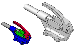
- Realistic. This default option is as close as possible to how the face would appear in the real world.
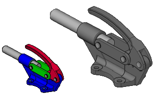
- Gooch. Uses cool and warm colors instead of dark and light to enhance the display of faces that might be shadowed and difficult to see in a realistic display.
- None. Does not apply a face style. Other face settings are disabled.
This face style displays edges with all hidden lines removed.
Shows details of 3D surface or solid by using warm colors for lighted areas and cool colors for darker areas. Only objects without applied materials show this face style.
- Lighting Quality
-
Sets the method for interpolating colors for faces on 3D solids and surfaces in the current viewport (VSLIGHTINGQUALITY system variable)
- Faceted.
- Smooth.
- Smoothest shows a high quality smooth appearance, but it will only produce a visible improvement if the “Per-Pixel Lighting” hardware effect option is turned on in the Manual Performance Tuning Dialog box.
This setting is the least resource intensive, but it displays curved surfaces as faceted approximations.

This default setting provides a smooth display without hardware acceleration.

To display at this setting, the Per-Pixel Lighting setting needs to be turned on in the Manual Performance Tuning dialog box from the 3DCONFIG command.

- Color
-
Controls the display of colors on faces. (VSFACECOLORMODE system variable)
- Normal. Does not apply a face color modifier.
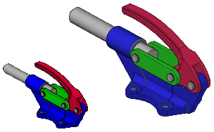
- Monochrome. Displays the model in shades of the color you specify (VSMONOCOLOR system variable).
- Tint. Changes the hue and saturation value of face colors.
- Desaturate. Softens the color by reducing its saturation component by 30 percent.
The monochrome color used is the color value stored in the VSMONOCOLOR system variable.

The tint color is determined by the hue and saturation settings of the color value stored in the VSMONOCOLOR system variable.

The color saturation of 3D solids and surfaces is reduced by 30 percent.

- Opacity
-
Controls the opacity or transparency of faces in a viewport. (VSFACEOPACITY system variable)
Materials and Color
Controls the display of materials and color on faces.
- Materials
-
Controls whether materials and textures are displayed. (VSMATERIALMODE system variable)
- Monochrome Color/Tint Color
-
Displays the Select Color dialog box, where you select the monochrome or tint color, depending on the face color mode. This setting is not available when face color mode is set to Normal or Desaturate. (VSMONOCOLOR system variable)
Environment Settings
Control shadows and background.
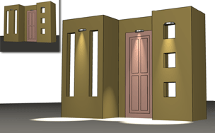
- Shadows
-
Controls the display of shadows.
Note: To display full shadows, hardware acceleration is required. When Geometry Acceleration is off, full shadows cannot be displayed. (To access these settings, enter 3dconfig at the Command prompt. In the Adaptive Degradation and Performance Tuning dialog box, click Manual Tune.) - Backgrounds
-
Controls whether backgrounds are displayed in the viewport. (VSBACKGROUNDS system variable)
Edge Settings
Control how edges are displayed.
- Show
-
Sets edge display to Facet Edges, Isolines, or None. (VSEDGES system variable)
- Color
-
Sets the color for edges. (VSEDGECOLOR system variable)
Edge Modifiers
Controls settings that apply to all edge modes except None.
- Line Extensions
-
Makes lines extend beyond their intersection, for a hand-drawn effect. The button turns the overhang effect on and off. When it is on, you can change the setting. (VSEDGELEX system variable)
- Jitter Button and Setting
-
Makes lines appear sketched. (VSEDGEJITTER system variable)
- Crease Angle
-
Sets the angle at which facet edges within a face are not shown, for a smooth effect. This option is available when the VSEDGES system variable is set to display facet edges. (VSEDGESMOOTH system variable)
- Halo Gap %
-
Specifies the size of a gap to be displayed where an object is hidden by another object. This option is available when the Conceptual or 3D Hidden visual styles, or a visual style based on them, is selected. When the halo gap value is greater than 0, silhouette edges are not displayed. (VSHALOGAP system variable)
Silhouette Edges
Controls settings that apply to silhouette edges. Silhouette edges are not displayed on wireframe or transparent objects. (VSSILHEDGES system variable)
- Show
-
Controls the display of silhouette edges. (VSSILHEDGES system variable)
- Width
-
Specifies the width at which silhouette edges are displayed. (VSSILHWIDTH system variable)
Occluded Edges
Controls settings that apply to all edge modes except None.
- Show
-
Controls whether occluded edges are displayed. (VSOCCLUDEDEDGES system variable)
- Color
-
Sets the color for occluded edges. (VSOCCLUDEDCOLOR system variable)
- Linetype
-
Sets a linetype for occluded edges. (VSOCCLUDEDLTYPE system variable)
Intersection Edges
Controls settings that apply to intersection edges when edge mode is set to Facet Edges.
- Show
-
Controls whether intersection edges are displayed. (VSINTERSECTIONEDGES system variable)
Note:To increase performance, turn off the display of intersection edges.
- Color
-
Sets the color for intersection edges. (VSINTERSECTIONCOLOR system variable)
- Linetype
-
Sets a linetype for intersection edges. (VSINTERSECTIONLTYPE system variable)
Lighting Settings
Controls lighting-related effects.
- Exposure Control
-
Controls the size of highlights on faces without materials. (VSFACEHIGHLIGHT system variable)
- Shadow Display
-
Controls the display of shadows in the viewports. Turn shadows off to increase performance. (VSSHADOWS system variable)
- Mapped Object Shadows. Displays full shadows.
- Ground Shadows.
- Off.