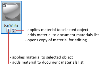
A material is defined by a number of properties. The available properties depend on the selected material type.
You cannot modify the materials in the Autodesk materials library, but you can use them as a basis for new materials. The Materials Editor provides property settings such as glossiness, transparency, highlights, and texture. The available property settings change, depending on the type of material you are updating.
To edit the settings, you can double-click a materials swatch or use the shortcut menu.

Update a Generic Material
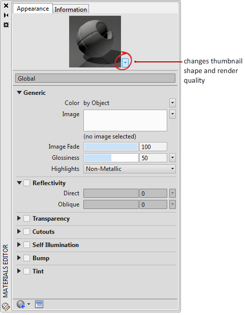
Edit an existing material (provided in the Autodesk materials library), or start with a generic material. The changes you make are displayed in the material swatch preview. You can change the shape of the image that is displayed in the preview.

Default Generic material has the following properties.
-
Color
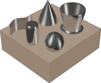
The color of a material on an object is different in different areas of the object. For example, when you look at a red sphere, it does not appear to be uniformly red. The sides away from the light appear to be a darker red than the sides facing the light. The reflection highlight appears the lightest red. In fact, if the red Sphere is very shiny, its highlight may appear to be white.
You can assign a color or a custom texture, which can be either an image or a procedural texture.
-
Image
Controls the base diffuse color map of the material. The diffuse color is the color that an object reflects when illuminated by direct daylight or artificial light.
-
Image Fade
Controls the composite between the base color and the diffuse image. The image fade property is only editable if an image is used.
-
Glossiness
The reflective quality of the material defines the degree of glossiness or dullness. To simulate a glossy surface, the material has a small highlight, and its specular color is lighter, perhaps even white. A duller material has a larger highlight that is closer to the main color of the material.
-
Highlights
Controls the means for deriving specular highlights of the material. The Metallic setting disperses light according to the angle of the light on the object (anistropic). Metallic highlights are the color of the material. Non-metallic are the color of the lights hitting the material.

Use Other Properties for Special Effects
The following properties can be used to create specific effects. Additional properties are available, depending on the type of material.
-
Reflectivity
Reflectivity simulates a scene reflected on the surface of a shiny object. For reflectivity maps to render well, the material should be shiny, and the reflection image itself should have a high resolution (at least 512 by 480 pixels). The Direct and Oblique sliders control the level of reflections and the intensity of the specular highlight on surfaces.
-
Transparency
A completely transparent object allows the passage of light through it. At 1.0, the material is completely transparent, and at 0.0, the material is completely opaque. The effect of transparency is best previewed against a pattern background.
The Translucency and Index of Refraction properties become editable only when the Transparency value is greater than 0. A translucent object, such as frosted glass, lets some light pass through and scatters some light within the object. At 0.0, the material is not translucent; at 1.0, the material is as translucent as possible.
The index of refraction controls the degree to which light rays are bent as they pass through the material and thus distort the appearance of objects on the other side of the object. For example, at 1.0, the object behind the transparent object is not distorted. At 1.5, the object is distorted greatly, as if it were seen through a glass marble.
-
Cutouts
Cutouts maps make the material partially transparent, giving a perforation effect based on a grayscale interpretation of a texture. You can select an image file to use for cutouts mapping. Lighter areas of the map render as opaque and darker areas render as transparent.
When you use transparency for frosting or translucent effects, reflectivity is maintained. Cutout areas are not reflective.
-
Self-illumination
Self illumination maps make portions of an object appear to glow. For example, to simulate neon without using a light source, you could set a self illumination value greater than zero. No light is cast on other objects and the self-illuminated object does not receive shadows.
White areas of the map render as fully self illuminating. Black areas render with no self illumination. Gray areas render as partially self illuminating, depending on the grayscale value.
- Filter color creates the effect of a color filter over the illuminated surface.
- Luminance causes a material to simulate being lit within a photometric light source. How much light is emitted is a selected value in photometric units. No light is cast on other objects.
- Color temperature sets the color of the self illumination.
-
Bump
You can select an image file or procedural maps to use for mapping. Bump mapping makes an object appear to have a bumpy or irregular surface. When you render an object with a bump-mapped material, lighter (whiter) areas of the map appear to be raised and darker (blacker) areas appear to be low. If the image is in color, the gray-scale value of each color is used. Bump mapping increases rendering time significantly but adds to the realism.
Use bump maps when you want to take the smoothness off a surface, or to create an embossed look. Keep in mind, however, that the depth effect of a bump map is limited because it does not affect the profile of the object and cannot be self-shadowing. If you want extreme depth in a surface, you should use modeling techniques instead. The bumps are a simulation created by perturbing face normals before the object is rendered. Because of this, bumps do not appear on the silhouette of bump-mapped objects.
The Bump map slider adjusts the degree of bumpiness. Higher values render as higher relief and negative values inverses the relief.
Use Amount to adjust the height of the bump. Higher values render as higher relief and low values render as low relief. Grayscale images make effective bump maps.
-
Tint
Sets the hue and saturation value of the color mixed with white.