Learn some best practices for mesh modeling.
Mesh modeling, with its enhanced modeling capabilities, offers a way to create more fluid, free-form designs. Keep these tips in mind as you work.
Model a mesh before you smooth it.
Mesh modeling is a powerful way to design, but higher levels of smoothness increase complexity and can affect performance. You can work more efficiently if you complete editing operations such as gizmo editing, extrusion, and face splitting, on mesh objects that have not been smoothed. (That is, their level of smoothness is 0.)
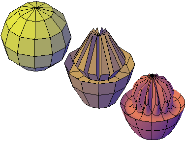
mesh sphere modeled by grip editing and extrusion, then smoothed
You can quickly switch between the levels of smoothness in the Properties palette to get a preview of how your activities affect the smoothed mesh.
Refine or split a face instead of refining the entire mesh.
Refinement is a powerful way to subdivide faces. However, by increasing the number of faces, you add to the overall complexity of the model. In addition, refining an entire mesh object resets the base level of smoothness to 0. This change can result in a dense grid that can no longer be simplified. For best results, avoid refining the object, and refine or split only the individual faces that require more detailed modeling.

mesh box, refined mesh box, and mesh box with one face refined
Refining individual faces does not reset the level of smoothness for the object.
Crease edges to help limit distortion when the mesh is smoothed.
Creased edges can be set to maintain their sharpness, no matter how much the mesh is smoothed. You may also need to crease the edges in surrounding faces to obtain the result you want.
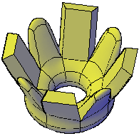
extruded faces on mesh torus, creased and not creased
Creasing set to Always retains its sharpness after smoothing. If you set a crease value, the creased edge becomes smoother at the equivalent level of smoothness.
Use gizmos to model faces, edges, and vertices.
3D Move, 3D Rotate, and 3D Scale gizmos can be used to modify entire mesh objects, or specific subobjects.
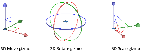
For example, you can rotate and scale an individual face using the 3D Move, Rotate, and Scale gizmos.
By constraining the modifications to a specified axis or plane, gizmos help you avoid unexpected results. The default gizmo is displayed whenever you select an object in a view that uses a 3D visual style. (You can also suppress this display.) Therefore, you do not have to explicitly start the 3D Move, 3D Rotate, or 3D Scale command to initiate these activities. You just need to select an object.
When a gizmo is selected, you can use the shortcut menu to switch to a different type of gizmo.
Use subobject selection filters to narrow the available selection candidates.
In a smoothed mesh, trying to select a subobject can be difficult unless you turn on subobject selection (shortcut menu). By specifying that the selection set is limited to faces, edges, vertices, or even solid history subobjects, you can restrict which subobject type is available for selection.
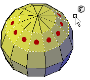
mesh faces selected when the face subobject selection filter is on
A filter is valuable for selecting mesh vertices, which are not highlighted as you move over them.
To select the entire mesh object, turn off the subselection filters.
Model by extruding faces.
A key difference between gizmo editing and extrusion occurs in the way each face is modified. With gizmo editing, if you select and drag a set of faces, adjacent faces are stretched to accommodate the modification. When the object is smoothed, the adjacent faces adapt to the new location of the face.
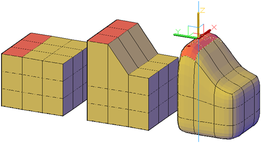
mesh faces extended using 3D Move gizmo
Mesh extrusion, however, inserts additional faces to close the gap between the extruded face and its original surface. With mesh extrusion, you can set whether adjacent faces are extruded as a unit (joined) or separately (unjoined).
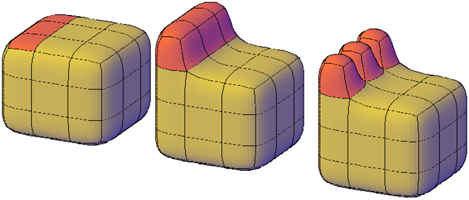
mesh faces extruded, then smoothed
If you are working on an object that has not been smoothed, try smoothing it periodically to see how the extrusion is affected.
Convert between mesh and 3D solids or surfaces.
Mesh modeling is powerful, but it cannot do everything that solid modeling can do. If you need to edit mesh objects through intersection, subtraction, or union, you can convert a mesh to a 3D solid or surface. Similarly, if you need to apply creasing or smoothing to a 3D solid or surface, you can convert it to a mesh.
Keep in mind that not all conversions retain complete fidelity to the shape of the original object. Avoid switching between object types more than once, if possible. If you notice that the conversion modifies the shape of the object in an unacceptable way, undo the conversion and try again with different settings.
The Mesh Tessellation Options dialog box (MESHOPTIONS) controls the smoothness and shape of the faces for 3D solids or surfaces that are converted to meshes. Although you can convert an object to a mesh without opening this dialog box (MESHSMOOTH), you can more easily experiment with different conversion settings by launching the conversion operation from within the dialog box.
The MESHSMOOTHCONVERT system variable sets whether the mesh objects that you convert to 3D solids or surfaces are smoothed or faceted, and whether their co-planar faces are optimized (merged).
You might have trouble converting some non-primitive mesh to solid objects due to the following problems:
- Gaps in the mesh. If you notice gaps, you can sometimes close them by smoothing the mesh or by refining the faces that are adjacent to the gap.

mesh torus that has been twisted using 3D Rotate at various smoothing levels
You can also close holes by using MESHCAP.
In some cases, you can also obtain better results by using hardware acceleration to improve your graphics system.
- Intersecting mesh faces. Be especially careful not to create self-intersections as you move, rotate, or scale subobjects. (You create self-intersections when you cause one or more faces to cross or intersect other faces in the same mesh model.) View the mesh from several viewpoints to ensure you create a viable model.
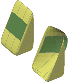
mesh wedge with front faces dragged past the back faces
Mesh objects that cannot be converted to solids can often be converted to surfaces instead.
Avoid merging faces that wrap a corner
When you merge faces, you can create a mesh configuration in which the merged face wraps a corner. If a resulting face has a vertex that has two edges and two faces, you cannot convert the mesh to a smooth 3D solid object.
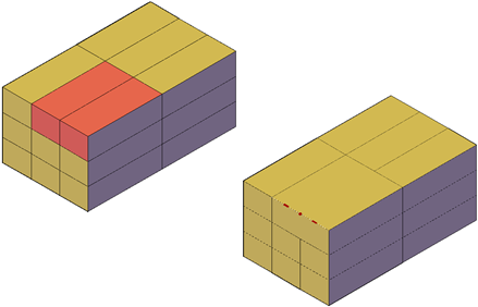
One way to resolve this problem is to convert the mesh to a faceted solid instead of a smooth solid. You might also be able to repair the problem by splitting the adjacent faces, starting at the shared vertex (MESHSPLIT).