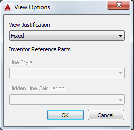
Defines various settings that pertain to drawing view geometry.
This dialog box specifies how to anchor the view geometry , and how to display Inventor Reference Parts.
List of Options
View Justification
Specifies how to anchor a view, when the view grows or shrinks due to an update operation.

If a view is “centered”, the view grows/shrinks about its center. This is typically used for views at the center of a layout.
If a view is “fixed”, unchanged model geometry remains in the same location as it was prior to the model change. This option is often preferred as less "shifting" occurs. However, this could result in the view overlapping the drawing border and title block.
Orthogonal projected views inherit the parent view justification setting by default. This is because an alignment constraint exists between parent views and projected views. In such a case, View Justification is not available for projected views. However, if the alignment constraint is broken, View Justification becomes available.
Inventor Reference Parts
- Line Style
-
Specifies the line type to use for reference parts (parts that are placed in the model to add context to it).
If you choose the “As Reference” option, the line type is derived from the layer Reference Layer. This uses the phantom line type by default.
If you choose the "As Parts" option, the line type is derived from the standard layers used for all other parts.
If you choose the “Off” option, all reference parts become invisible.

- Hidden line calculation
-
Specifies how hidden lines are calculated.
If you choose the “Separate” option, hidden lines for reference lines are calculated separately from other parts.
If you choose the combined option, hidden lines for reference parts are calculated together with all other parts.