A wire network consisting of three or more interconnected components introduces potential unknowns into a from/to connection report. Does A connect to B and then jumper to C or does C connect to A and jumper to B?
By default, AutoCAD Electrical reports from/to connections on a single network by first grouping devices by common Location codes and sequentially reports the inter-wiring of each group. It then ties each common Location group with a single from/to wire connection. For wire connections with the same Location group (or if all devices have the same Location value or no Location value), AutoCAD Electrical attempts to sort the wire connections by physical location on the drawing and report the from/to connections in that order.
AutoCAD Electrical provides several methods to more specifically define wire connection sequencing. You control how AutoCAD Electrical analyzes the circuits (such as the order of the contents in the WFRM2ALL table in the project’s scratch database file) and how from/to connection information is output to various reports or annotated on to physical footprint representations (using the Wire Annotation of Panel Footprint tool).
Angled Tee Wire Connection Method
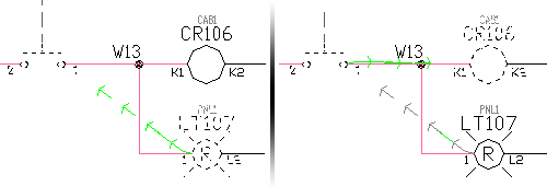
The use of angled tee wire connections can influence the wire connection sequence reporting. The orientation of the tee symbol defines the sequencing. Each symbol carries attribute WDWSEQ with a three-digit value indicating the preferred wire sequencing order. The 90-degree turn or the straight-through section (depending on the style of the angled tee symbol) indicates the beginning of the sequence. The 45-degree turn is the secondary connection. AutoCAD Electrical reports each wire connection as it is shown.
This method of influencing from/to connection sequence reporting can fail to give expected results when the orientation of multiple angled tee connection symbols results in either:
- An illogical or impossible connection configuration.
- More than two wires routed to a given wire connection point on a device.
Set the automatic angled wire tee insert mode (instead of tee intersection dots) in the Project Properties  Styles dialog box.
Schematic Wire Connection Sequence Method
This method involves touching the connection sequence for each wire network containing three or more interconnected components. AutoCAD Electrical places an incrementing connection sequence value on each wire connection point. It is saved as a three-digit Xdata value, starting with “001” on the wire connection attribute. When any of the AutoCAD Electrical From/To reports processes wire networks containing this incrementing sequencing data, the from/to wire connections order accordingly.
Direct-to-Terminal Wire Connection Sequence Method
This method defines additional Direct-to-Terminal wire connection sequences. For example, one side of a schematic terminal might be connected to three devices. A specific wire connection sequence (using the Schematic Wire Connection sequence method previously described) can be defined to force the connection reporting. It is limited to reporting the terminal as a common connection point between only two of the three devices. The third device would default to being reported as jumpered to one of the other two devices. Additional secondary Direct-to-Terminal sequences can be defined so that the third device can be sequenced directly to the terminal. You can also directly sequence two terminals together. The result is that the From/To connection reporting shows all three devices tied directly to the terminal.
Level/Routing Method
This method brings the panel layout into play to affect the reporting sequence in the various From/To reports. The panel layout or panel wiring diagram layout representations are assigned level/routing codes consisting of a four-level hierarchy plus a sequence number. As schematic wire networks are processed for the From/To reports, the existence of panel layout representations that are marked with level/routing values is checked. If this information is found for all the devices of the network being processed, the connections of the network are sorted by this hierarchy and sequence information. The result is a set of From/To reported connections that follow the level/routing data carried by the layout.