Creates a set of PLC I/O drawings from spreadsheet data.
Find Command entry:
AESS2PLC
Command entry:
AESS2PLC
Select the spreadsheet output file and click Open.
The PLC I/O requirements in spreadsheet or database format can drive automatic generation of the I/O schematic drawings. The program finds the columns containing the information necessary to generate the drawings. Your settings can define the order of the columns. All columns are optional except for Module part number (Code).
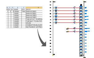
AutoCAD Electrical reads in your information (.xls, .mdb, or .csv format) and then constructs a set of PLC I/O wiring diagrams directly from your data. Ladders and modules insert automatically, breaking at the bottom of one ladder and continuing on the next (or on to the next drawing).
Settings
Select a PLC settings file (.wdi) to use. The default is to use the settings in the WDIO.LSP file. Specify the settings to use by entering a file name in the box or clicking Browse to select a file. The path to the selected WDI file displays underneath the edit box. If you enter the name of the .wdi file, AutoCAD Electrical searches for the file in the standard search locations in the following order:
- User subdirectory: C:\Users\{username}\AppData\Roaming\Autodesk\AutoCAD Electrical {version}\{release}\{country code}\Support\User\
- Active project's .wdp file subdirectory
- Symbol library paths defined for the active project
- AutoCAD Electrical lookup subdirectory: C:\Users\{username}\Documents\Acade {version}\AeData\
- AutoCAD Electrical support (C:\Program Files [(x86)]\Autodesk\AutoCAD {version}\Acade\Support\{language code}\.)
- Current Directory
- All paths defined under AutoCAD Options
 Files Support Files Search Path
Click Setup to display the Spreadsheet to PLC I/O Utility Setup dialog box. Use it to modify and save new setting configurations.
Ladder Reference Numbering
| Start | Specifies the value for the beginning line reference number for the first ladder of the first drawing. Leading zeros and embedded alpha characters are supported for line reference numbering. |
| Index | Defines if you want your line reference numbers to sequence by 1 (default) or by some other amount. |
| Column to column | Indicates whether to use the next sequential number for the first ladder on each successive column or to use the specified value to skip for the first ladder reference of the next column. |
| Drawing to drawing | Indicates whether to use the next sequential number for the first ladder on each successive drawing or to use the specified value to skip for the first ladder reference of the next drawing. |
Module Placement
There are three options related to module placement. Define if you want each I/O module to start at the top of a ladder, if you want the module built in a ladder with the previous module only if it fits completely, or if you want the module to be built in the same ladder with the previous module and split if necessary to fill the ladder.
| Include unused/extra connections | You may have PLC modules with terminal connections that are unused. Usually AutoCAD Electrical leaves them out and the module is built without showing these terminal connections. Select it to include the connections in the PLC module. If you select to place modules within the same ladder, enter the number of rungs to skip between modules. Note:
If you want to show these connections, include them in the Attributes column of the Module Terminal Information table of the ace_plc.mdb file with ";\\SPECIAL=INCLUDE" following the block information or by selecting "When Including Unused" or "When Excluding Unused" in the Show column of the PLC Database File Editor dialog box. When a module is selected that contains some of these terminals, they are included if you select this option. |
| Allow pre-defined breaks | Your PLC modules automatically break at a given point when a "\\SPECIAL=BREAK" code is encountered in the block of parametric data of the module. |
Drawing File Creation
| Use active drawing | Indicates to use the open and active drawing file to begin the PLC placement process. Note:
It is unavailable if a Starting file name is specified. |
| Starting file name | Specifies the drawing file to begin with for your PLC drawings. Enter a name or click Browse to select a file. The .dwg extension is not required and the file is saved in the same folder as the active .wdp file. |
| Pause between drawings/Free run | Your spreadsheet may contain enough information to generate multiple drawings. Select Pause between drawings to stop between each drawing or select Free run if you want the program to run completely to the end without stopping. Note:
When you select Pause Between Drawings, a single drawing is generated and then a dialog box opens allowing you to adjust settings, select to do a free run, or continue with a pause between drawings. The Use active drawing option is disabled. |
|
Sheet |
If your ladders use the AutoCAD Electrical Sheet parameter you can enter a value for the optional sheet number. |
|
Add new drawing to active project |
Adds newly created drawings to the active project. The new drawings are added to the end of the project’s drawing list. |
Save
Saves the setup information and settings in a .wdi file to reuse.