Creates multiple copies of objects in a pattern.
List of Options
The following options are displayed.
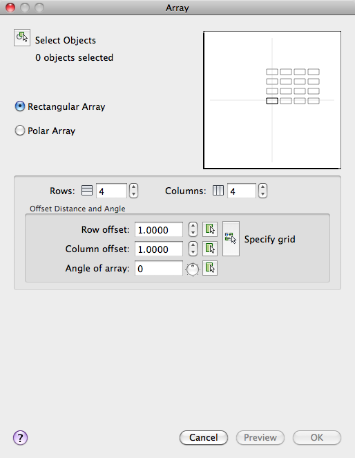
Select Objects
Specifies the objects used to construct the array. You can select objects before or after the Array dialog box is displayed. To select objects when the Array dialog box is displayed, choose Select Objects. The dialog box temporarily closes. When you finish selecting objects, press Enter. The Array dialog box is redisplayed, and the number of objects selected is shown below the Select Objects button.
Preview Area
Shows a preview image of the array based on the current settings in the dialog box. The preview image is dynamically updated when you move to another field after changing a setting.
Rectangular Array
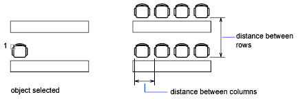
Creates an array of rows and columns of copies of the selected object.
- Rows
-
Specifies the number of rows in the array.
If you specify one row, you must specify more than one column. If you specify a large number of rows and columns for the array, it might take a while to create the copies. By default, the maximum number of array elements that you can generate in one command is 100,000. The limit is set by the MAXARRAY setting in the registry. To reset the limit to 200,000, for example, enter (setenv "MaxArray" "200000") at the Command prompt.
- Columns
-
Specifies the number of columns in the array.
If you specify one column, you must specify more than one row. If you specify a large number of rows and columns for the array, it might take a while to create the copies. By default, the maximum number of array elements that you can generate in one command is 100,000. The limit is set by the MAXARRAY setting in the registry. To reset the limit to 200,000, for example, enter (setenv "MaxArray" "200000") at the Command prompt.
Offset Distance and Angle
Provides a space for you to specify the distance and direction of the array's offset.
- Row Offset
-
Specifies the distance (in units) between rows. To add rows downward, specify a negative value. To specify row spacing with the pointing device, use the Pick Both Offsets button or the Pick Row Offset button.
- Column Offset
-
Specifies the distance (in units) between columns. To add columns to the left, specify a negative value. To specify column spacing with the pointing device, use the Pick Both Offsets button or the Pick Column Offset button.
- Angle of Array
-
Specifies the angle of rotation. This angle is normally 0, so the rows and columns are orthogonal with respect to the X and Y drawing axes of the current UCS. You can change the measurement conventions for angles using UNITS. The ANGBASE and ANGDIR system variables affect the angle of arrays.
- Pick Row Offset
-
Temporarily closes the Array dialog box so that you can use the pointing device to specify the distance between rows. ARRAY prompts you to specify two points and uses the distance and direction between the points to specify the value in Row Offset.
- Pick Column Offset
-
Temporarily closes the Array dialog box so that you can use the pointing device to specify the distance between columns. ARRAY prompts you to specify two points and uses the distance and direction between the points to specify the value in Column Offset.
- Pick Angle of Array
-
Temporarily closes the Array dialog box so that you can specify the angle of rotation by entering a value or using the pointing device to specify two points. You can change the measurement conventions for angles using UNITS. The ANGBASE and ANGDIR system variables affect the angle of arrays.
- Pick Both Offsets
-
Temporarily closes the Array dialog box so that you can use the pointing device to set the row and column spacing by specifying two diagonal corners of a rectangle.
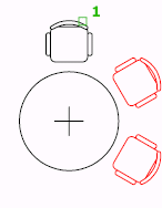
Polar Array
Creates an array by copying the selected objects around a specified center point.
- Center Point
-
Specifies the center point of the polar array. Enter coordinate values for X and Y, or choose Pick Center Point to use the pointing device to specify the location.
- Pick Center Point
-
Temporarily closes the Array dialog box so that you can use the pointing device to specify the center point in the drawing area.
Spacing Methods
Specifies the method and values used to position objects in the polar array.
- Method
-
Sets the method used to position objects. This setting controls which of the Method and Value fields are available for specifying values. For example, if the method is Total Number of Items & Angle to Fill, the related fields are available for specifying values; the Angle Between Items field is not available.
- Total Number of Items
-
Sets the number of objects that appear in the resultant array. The default value is 4.
- Angle to Fill
-
Sets the size of the array by defining the included angle between the base points of the first and last elements in the array. A positive value specifies counterclockwise rotation. A negative value specifies clockwise rotation. The default value is 360. A value of 0 is not permitted.
- Pick Angle to Fill
-
Temporarily closes the Array dialog box so that you can define the included angle between the base points of the first and last elements in the array. ARRAY prompts you to select a point relative to another point in the drawing area.
- Angle Between Items
-
Sets the included angle between the base points of the arrayed objects and the center of the array. Enter a positive value. The default direction value is 90.
Note: You can choose the Pick buttons and use the pointing device to specify the values for Angle to Fill and Angle Between Items. - Pick Angle Between Items
-
Temporarily closes the Array dialog box so that you can define the included angle between the base points of the arrayed objects and the center of the array. ARRAY prompts you to select a point relative to another point in the drawing area.
Rotation and Base Point
Specifies the rotation and object base point for the polar array.
- Rotate Items as Copied
-
Rotates the items in the array, as shown in the preview area.
- Use Object Base Point
-
Uses the default base point of the object to position the arrayed object. To manually set the base point, clear this option.
Base point settings by object
Object type
Default base point
Arc, circle, ellipse
Center point
Polygon, rectangle
First corner
Donut, line, polyline, 3D polyline, ray, spline
Starting point
Block, paragraph text, single-line text
Insertion point
Construction lines
Midpoint
Region
Grip point
- Base Point
-
Note: To avoid unexpected results, set the base point manually if you are constructing a polar array and do not want to rotate the objects.
Preview
Closes the Array dialog box and displays the array in the current drawing.