Specifies page layout and plotting device settings.
Summary
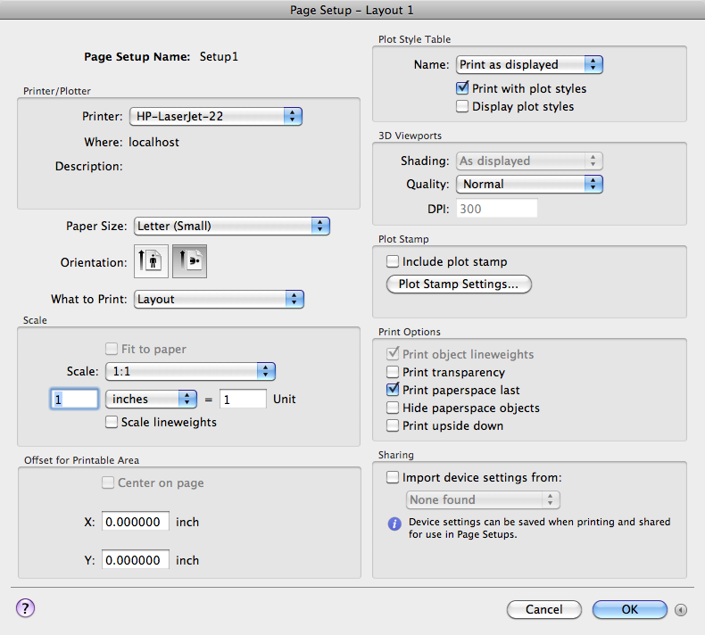
The Page Setup dialog box is displayed in the following cases:
- When you create a new page setup through the Page Setup Manager
- When you modify an existing page setup through the Page Setup Manager
- When you modify an existing page setup through the Print dialog box
The page setup settings that you specify are stored with the layout and can be applied to other layouts or imported into other drawings.
List of Options
The following options are displayed.
Page Setup Name
Displays the name of the current page setup.
Printer/Plotter
Specifies a configured output device to use when printing layouts.
- Printer
-
Lists the available system printers from which you can select to print the current layout.
- Where
-
Displays the physical location of the output device specified in the currently selected page setup.
- Description
-
Displays descriptive text about the output device specified in the currently selected page setup.
Paper Size
Displays standard paper sizes that are available for the selected plotting device.
If the selected plotter does not support the layout's selected paper size, a warning is displayed, and you can select the plotter's default paper size or a custom paper size.
Orientation
Specifies the orientation of the drawing on the paper for plotters that support landscape or portrait orientation.
- Portrait
-
Orients and plots the drawing so that the short edge of the paper represents the top of the page.
- Landscape
-
Orients and plots the drawing so that the long edge of the paper represents the top of the page.
What to Print
Specifies the area of the drawing to be plotted.
- Display
-
Plots the view in the current viewport in the current layout.
- Extents
-
Plots the portion of the current space of the drawing that contains objects. All geometry in the current layout is plotted. The drawing may be regenerated to recalculate the extents before plotting.
- Window
-
Plots any portion of the drawing that you specify. When you specify the two corners of the area to plot, the Window button becomes available.
Click the Window button to use the pointing device to specify the two corners of the area to be plotted, or enter coordinate values.
- Model/Layout Views
-
Plots a view that was previously saved with the -VIEW command.
- Layout/Limits
-
When plotting a layout, plots everything within the printable area of the specified paper size, with the origin calculated from 0,0 in the layout.
When plotting from the Model layout, plots the entire drawing area that is defined by the grid limits. If the current viewport does not display a plan view, this option has the same effect as the Extents option.
Scale
Controls the relative size of drawing units to plotted units.
- Fit to Paper
-
Scales the plot to fit within the selected paper size and displays the custom scale factor in the Scale, Inch =, and Units boxes.
- Scale
-
Defines the exact scale for the output. Custom defines a user-defined scale. You can create a custom scale by entering the number of inches (or millimeters) equal to the number of drawing units.
- Inch(es) =/mm =
-
Specifies the number of inches or millimeters equal to the specified number of units.
- Inch/mm
-
Specifies inches or mm for display of units. The default is based on the paper size and changes each time a new paper size is selected.
- Unit
-
Specifies the number of units equal to the specified number of inches or millimeters.
- Scale Lineweights
-
Scales lineweights in proportion to the plot scale. Lineweights normally specify the line width of output objects and are output with the line width size regardless of the scale.
Offset for Printable Area
Specifies an offset of the plot area relative to the lower-left corner of the printable area or to the edge of the paper, depending on the value of the PLOTOFFSET system variable.
The printable area of a drawing sheet is defined by the selected output device and is represented by a dashed line in a layout. When you change to another output device, the printable area may change.
You can offset the geometry on the paper by entering a positive or negative value in the X and Y offset boxes. The plotter unit values are in inches or millimeters on the paper.
- Center on Page
-
Automatically calculates the X and Y offset values to center the plot on the paper.
- X
-
Specifies the plot origin in the X direction relative to the value of PLOTOFFSET.
- Y
-
Specifies the plot origin in the Y direction relative to the value of PLOTOFFSET.
More/Fewer Options
Expands or collapses the dialog box to show or hide additional output options.
Plot Style Table
Sets the plot style table to use with the page setup.
- Name
-
Displays a list of available plot style tables.
- Print with Plot Styles
-
Specifies whether plot styles applied to objects and layers are printed.
- Display Plot Styles
-
Controls whether the properties of plot styles assigned to objects are displayed on the screen.
3D Viewports
Specifies how shaded and rendered viewports are plotted and determines their resolution levels and dots per inch (dpi).
- Shading
-
Specifies how views are plotted. To specify this setting for a viewport on a layout tab, select the viewport and then, on the Mac OS menu bar click Tools
 Palettes Properties.
 From the Model layout, you can select from the following options:
- As Displayed: Plots objects the way they are displayed on the screen.
- Legacy Wireframe: Plots objects in wireframe regardless of the way they are displayed on the screen.
- Legacy Hidden: Plots objects with hidden lines removed regardless of the way they are displayed on the screen.
- Conceptual: Plots objects with the Conceptual visual style applied regardless of the way the objects are displayed on the screen.
- Hidden: Plots objects with the Hidden visual style applied regardless of the way the objects are displayed on the screen.
- Realistic: Plots objects with the Realistic visual style applied regardless of the way the objects are displayed on the screen.
- Shaded: Plots objects with Shaded visual style applied regardless of the way the objects are displayed on the screen.
- Shaded with Edges: Plots objects with Shaded with Edges visual style applied regardless of the way the objects are displayed on the screen.
- Shades of Gray: Plots objects with Shades of Gray visual style applied regardless of the way the objects are displayed on the screen.
- Sketchy: Plots objects with Sketchy visual style applied regardless of the way the objects are displayed on the screen.
- Wireframe: Plots objects with the Wireframe visual style applied regardless of the way the objects are displayed on the screen.
- X-ray: Plots objects with x-ray visual style applied regardless of the way the objects are displayed on the screen.
- Quality
-
Specifies the resolution at which shaded viewports are plotted.
You can select from the following options:
- Draft: Sets rendered and shaded model space views to be plotted as wireframe.
- Preview: Sets rendered and shaded model space views to be plotted at one quarter of the current device resolution, to a maximum of 150 dpi.
- Normal: Sets rendered and shaded model space views to be plotted at one half of the current device resolution, to a maximum of 300 dpi.
- Presentation: Sets rendered and shaded model space views to be plotted at the current device resolution, to a maximum of 600 dpi.
- Maximum: Sets rendered and shaded model space views to be plotted at the current device resolution with no maximum.
- Custom: Sets rendered and shaded model space views to be plotted at the resolution setting that you specify in the DPI box, up to the current device resolution.
- DPI
-
Specifies the dots per inch for shaded and rendered views, up to the maximum resolution of the current plotting device.
Plot Stamp
Controls the placement of a plot stamp on each layout and/or logs it to a file.
Plot stamp settings are specified in the Plot Stamp Settings dialog box, in which you can specify the information that you want applied to the plot stamp, such as drawing name, date and time, plot scale, and so on.
- Include Plot Stamp
-
Turns on plot stamping for the layout.
- Plot Stamp Settings
-
Displays the Plot Stamp Settings dialog box when Include Plot Stamp is selected.
Print Options
Specifies options for lineweights, transparency, and the order in which objects are plotted.
- Print Object Lineweights
-
Specifies whether lineweights assigned to objects and layers are printed.
- Print Transparency
-
Specifies whether object transparency is printed. This option should only be used when printing drawings with transparent objects.
- Print Paper Space Last
-
Prints model space geometry first. Paper space geometry is usually printed before model space geometry.
- Hide Paper Space Objects
-
Specifies whether the HIDE operation applies to objects in the paper space viewport. This option is available only from a named (paper space) layout. This setting is reflected in the output, but not in the display of the layout.
- Print Upside Down
-
Orients and prints the drawing upside-down.
Sharing
Allows you to import settings from a PC3 file.
- Import Device Settings From
-
Enables importing of settings from a PC3 file.
- PC3 Files List
-
Lists the available PC3 files that you can select from to import print settings file.
The program looks in the location specified by the value in Printer Support File Path
Printer Configuration Search Path under Application in the Application Preferences dialog box.