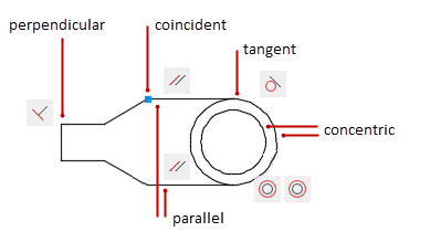
You can apply geometric constraints to associate 2D geometric objects together, or specify a fixed location or angle.
For example, you can specify that a line should always be perpendicular to another one, that an arc and a circle should always remain concentric, or that a line should always be tangent to an arc.
When you apply a constraint, you will notice three changes:
- The object that you select adjusts to conform to the specified constraint
- By default, a constraint icon displays near the constrained object as shown in the previous illustration: coincident constraints display as small. blue squares, and all other constraints display as gray icons
- A small blue glyph displays with your cursor when you move it over a constrained object
Once applied, constraints permit only those changes to the geometry that do not violate the constraints. This provides a method for exploring design options or making design changes while maintaining the requirements and specifications of the design.
The order in which you select two objects when you apply a constraint is important in some cases. Normally, the second object you select adjusts to the first object. For example, when you apply a perpendicular constraint, the second object you select will adjust to become perpendicular to the first.
You can apply geometric constraints to 2D geometric objects only. Objects cannot be constrained between model space and paper space..
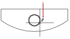
Specify Constraint Points
With some constraints, you can specify constraint points on objects instead of selecting the objects. This behavior is similar to that of object snaps, but the locations are limited to endpoints, midpoints, center points, and insertion points. For example, a coincident constraint can restrict the location of the endpoint of one line to the endpoint of another line.
The following glyph displays on an object as your cursor rolls over it. In this case, it indicates that the next constraint will be applied to the left endpoint of the horizontal line.
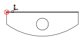
You use this glyph to confirm whether you are specifying the intended point to constrain.
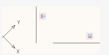
The fix, horizontal, and vertical constraint icons indicate whether the constraints are applied to an object or a point.
| Constraint | Point | Object |
|---|---|---|
| Fix |
|
|
| Horizontal |
|
|
| Vertical |
|
|
The symmetric constraint icons indicate whether it identifying a symmetrical point or object, or the symmetrical line.
| Constraint | Point | Object | Line |
|---|---|---|---|
| Symmetric |
|
|
|
A different set of constraint bar icons are displayed when a horizontal or vertical constraint is not parallel or perpendicular with the current UCS.
Use Fix Constraints
A fix constraint associates a constraint point on an object, or the object itself with a fixed location and angle with respect to the World Coordinate System.
It is often advisable to specify a fix constraint at an important geometric feature. This locks the location of that point or object, and prevents geometry from relocating when you make changes to the design.
When you fix an object, the angle of a line, or the center of an arc or circle is also fixed.Apply Multiple Geometric Constraints
You can apply multiple geometric constraints to objects either manually or automatically.
When you want to apply all essential geometric constraints to a design automatically, you can use AUTOCONSTRAIN with the objects that you select in your drawing. After applying constraints automatically, it is likely that you will need to apply and remove geometric constraints manually.
AUTOCONSTRAIN also provides settings in which you can specify the following options:
- What geometric constraints to apply
- What order to apply geometric constraints
- What tolerances are used to determine whether objects are horizontal, vertical, or touching
To fully constrain the size and proportions of a design, you will later need to apply dimensional constraints.
Delete Geometric Constraints
A geometric constraint cannot be modified, but you can delete it and apply a different one. Several constraint options, including Delete, are available from the shortcut menu that is displayed when you right-click a constraint icon in the drawing.
You can delete all constraints from a selection set in a single operation with DELCONSTRAINT.