Add duct fittings other than those specified by you in the Duct Routing Preference.
AutoCAD MEP adds fittings as you draw a duct run based on default fittings in the Duct Routing Preferences, or you can manually add a fitting to an existing segment or duct run. You can also add a fitting where you want to start a segment or run or customize the connection to a part.
Routing preferences specify the common fittings used for most duct layouts. However, the default duct parts catalog includes many other fittings you can use.
To add a duct fitting manually
- In the HVAC workspace, to select a fitting, click
 .
. Tip: You can also use the Fitting tool palette.
 - On the Properties palette General, click the part image next to Part.
- In the Select a Part dialog box, select a part from the catalog.
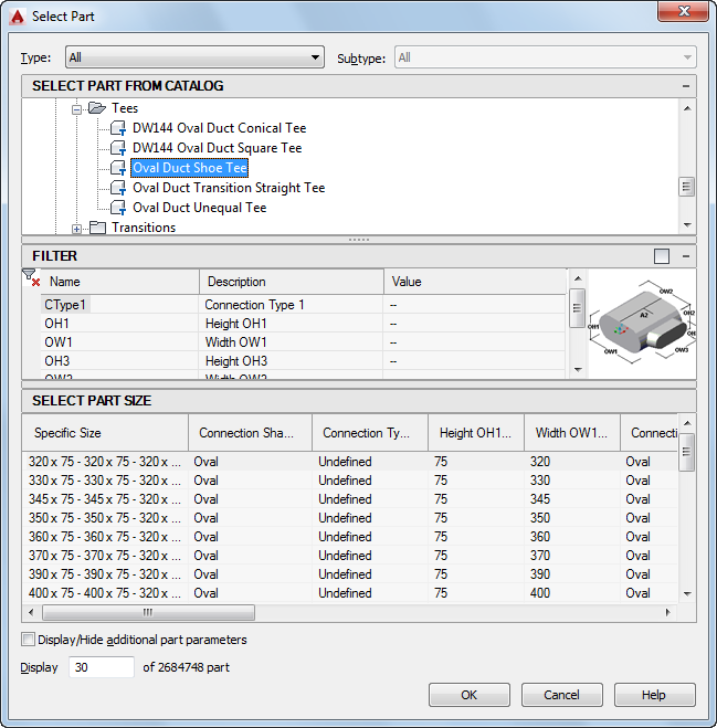
Select a Part dialog box
Under Select Part from Catalog, the dialog box organizes duct fittings based on shape type.
- (Optional) Select Display/Hide additional part parameters to expand the contents of the parameters table.
- Use the filter to sort through the list of parts. Note: The part catalogs and content locations determine the parts that you can select.
- Select a part size.
- On the Properties palette, under Placement, enter an elevation. Note: If you insert a fitting in an existing duct run, you do not need to specify the elevation. The fitting inherits the elevation and system settings from the duct run.
- Specify an insertion point in the drawing, and use the compass to specify a rotation angle.
You can use duct curve or end connectors to insert the fitting on an existing duct object.