The General tab in the Duct Layout Preferences dialog controls duct layout preferences for slope, elevation, labels, flow arrows and elbow preference.
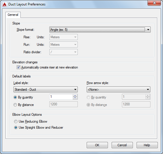
General tab
Slope preferences
Elevation preference
Label preferences
Flow arrow preferences
Elbow reducer preference
- On the General tab of the Duct Layout Preferences dialog, select a slope format.
Slope format affects the Slope property in the Properties palette. Slope format is stored with the drawing. The list includes the following formats:
Slope format Description Angle Expressed in degrees (for example, 2 degrees) Percentage Expressed as a percent, where 100%=45 degrees Percentage Expressed as a percent, where 100%=90 degrees Rise/Run Expressed as a fraction (for example, 1/48 or 1/100) Note: The Slope property in the Properties palette is displayed as a fraction. - Select drawing units for Rise and for Run.
The Units list is only turned on if you first selected a slope format. The units in the list are derived from the current profile and from selections made in the Drawing Setup dialog in AutoCAD Architecture. For example, for Metric, you can choose meters, millimeters, etc. For Imperial, you can choose feet or inches.
- Enter a Constant value.
You can only edit constant value for Rise if you previously selected Rise/Run with Constant Rise for Slope format. You can only edit constant value for Run if you previously selected Rise/Run with Constant Run for Slope format.
- Select slash (/) or colon (:) for the preferred ratio divider.
- Select Automatically create riser at new elevation to turn on this layout behavior.
- Select a label style.
Label preferences are stored in the registry.
Note: If you select None, skip the next step. - Select By quantity or By distance:
- For By quantity, enter the number of labels to add to each straight segment.
- For By distance, enter a segment length. If the segment length is less than the interval distance, a label is not automatically added to that segment.
- Select a flow arrow style from the list. Note: If you select None, skip the next step.
- Select By quantity or By Distance:
- For By quantity, enter the number of flow arrows to add to each straight segment.
- For By distance, enter a segment length. If the segment length is less than the interval distance, a flow arrow is not automatically added to that segment.
- Do one of the following:
- Select Use Reducing Elbow to add a single fitting when changing the direction of the duct run and the size of the duct.
- Select Use Straight Elbow and Reducer to add 2 fittings, an elbow and a reducer, when changing the direction of the duct run and the size of the duct.
The following examples show label, flow arrows, reducing elbow and straight elbow and reducer in a duct run:
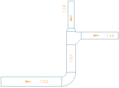
Lables
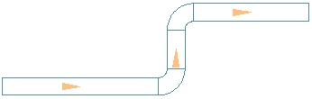
Flow Arrows Spaced Evenly, 1 per segment
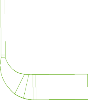
Reducing elbow
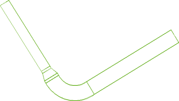
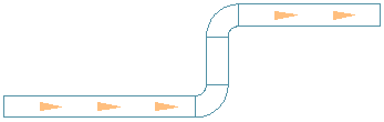
Straight elbow and reducer