1. To set cam properties
-
Click
 . Find
- In the Cam Design and Calculation dialog box, define the cam mechanism in the following sequence: Cam, Follower, Profile, and then Location.
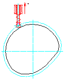
- Select a point in the drawing to specify the center of the cam and to insert the cam mechanism.
- Specify a start point for the cam movement.
- Specify the direction of movement for the follower in which the movement is considered as positive.
- Set the length of the horizontal axis to draw the displacement, velocity, and acceleration diagrams.
2. To set scale and resolution for the motion diagrams
- In the Cam Design and Calculation dialog box, click Motions.
- In the Options tab, select the diagrams you want to draw and set the scale and resolution for the curves.
3. To define segments for the cam-follower displacement curve
- In the Cam Design and Calculation dialog box, click Motions.
- In the Motion tab, select New. A dialog box displays.
- Choose Append from the displayed dialog box.
- In the Motion dialog box, specify the end angle for the first segment.
- Specify the elevation of the follower at the end of the segment.
- From the context button, set boundary conditions for the curve of the current segment.
- Select a type of motion from the list to define a velocity and acceleration curve.
- Set values for velocity and acceleration at the segment boundaries if you choose to override the calculated values.
- Click Apply to save data for the segment you defined.
- Click New to define the next segment in the displacement curve.
- Choose Append from the displayed dialog box.
- Repeat steps 4. through 9.
- Define as many segments to the curve as you like, until a 360° rotation is complete.
- In the Motion dialog box, choose OK.
4. To define strengths for the cam-follower mechanism
- In the Cam Design and Calculation dialog box, click Strength.
- Select the Loads tab to set the external forces acting on the follower.
- Select the Spring tab to define pre load and spring radii to keep the follower in contact with the cam.
- Select the Material tab to specify a type of material for cam and roller.
- Select the Arm tab to dimension and choose a material for the arm of the follower.
- Select the Friction tab to specify the frictional force between the arm and guide bushing.
5. To find an optimal cam shaft center
- In the Cam Design and Calculation dialog box, click Results.
- Select the Geometry tab.
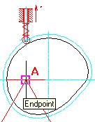
- To specify an optimal center point for the cam, click Center of Cam. A triangle is drawn in the drawing.
- In the drawing, select the point at the top angle of the triangle as the new cam center (point A). This gives the smallest possibly cam with the optimized pressure angle and radius of curvature for these two.
Note: You can choose any point within the area of the triangle as the cam center, but selection of point A, as shown in the picture above, yields the smallest possible cam for the given requirements.
6. To save cam data to a DXF or TXT file
- In the Cam Design and Calculation dialog box, click Export.
- Select the Relations tab to set the coordinate system.
- Select the File tab, and then select the curve whose data you want to save to a file.
- Set a precision when extracting NC data from the cam profile.
- From the Data Type, select the type of file to which you want to save this NC data, and then click Generate File.
- In the Save File dialog box, specify a location to save the file.