In this exercise, you will split a profile view so that the full elevation range of a layout profile fits in a shorter profile view.
This exercise continues from Exercise 3: Projecting Objects onto a Profile View.
Split a profile view
- Open Profile-5D.dwg, which is located in the tutorials drawings folder.
- Click tab
 panel drop-down
  .
. - In the Create Profile View wizard, on the General page, specify the following parameters:
- Select Alignment: Ridge Road
- Profile View Style: Standard
- On the left side of the wizard, click Profile View Height.
- On the Profile View Height page, specify the following parameters:
- Profile View Height: User Specified
- Maximum: 670.00’
- Split Profile View: Selected
The split profile view controls are now available. These controls allow you to select separate profile view styles for the first, intermediate, and last segments of the split profile view. For this exercise, accept the default split profile view settings.
- Click Next.
- On the Profile Display Options page, clear the Draw check boxes for all profiles except EG - Surface (1) and Layout (1). In the Layout (1) row, select the Split At option. This option specifies that the split occurs at the appropriate elevation of the layout profile and ensures that the entire layout profile will appear in the profile view.
- Scroll to the right until the Labels column is visible. In the EG - Surface (1) row, click the Labels cell.
- In the Pick Profile Label Set dialog box, select <None>. Click OK.
- Click Create Profile View.
- When prompted, pan and zoom to a clear area in the drawing window, then click to create the profile view.
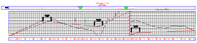
A new profile view is created. Notice that because you specified a shorter maximum height in step 7, the profile view grid is shorter than the other profile views in the drawing. In order to fit the profile in the shorter grid, the profile has been split in two segments. The full length and elevations of the red, layout profile are visible because you set the Split At setting to Layout (1) in step 6. Notice that there is a vertical axis in the middle of the profile view that displays the elevations for both split segments.
Modify the properties of the split profile view
- In Toolspace, on the Prospector tab, expand the AlignmentsCenterline AlignmentsRidge Road Profile Views collections.
Notice that a single new profile view (PV - (4)) was created.
- On the Prospector tab, right-click PV - (4). Click Properties.
- In the Profile View Properties dialog box, on the Elevations tab, under Elevation Range, change the Height to 15.000’.
- Click Apply.
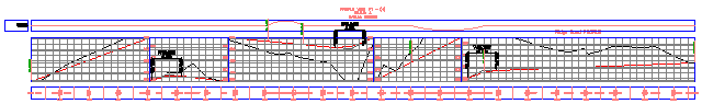
Notice that in the drawing window, the profile view has been split into five segments to accommodate the new height.
Now you will change the style of the first and last profile view segments.
- In the Profile View Properties dialog box, in the Split Profile View Data table, in the No. 1 row, in the Profile View Style column, click
 .
. - In the Pick Profile View Style dialog box, select Left & Bottom Axis. Click OK.
- Repeat steps 5 and 6 to change the Profile View Style in row No. 4 to Full Grid.
- Click OK.
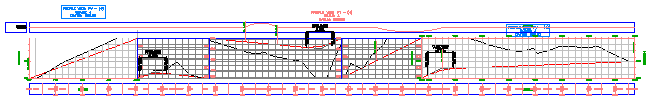
Three different profile view styles are displayed in the single profile view grid. While a split profile is displayed in a single profile view grid, it may have separate styles applied to each of its split segments.
To continue this tutorial, go to Exercise 6: Creating Multiple Profile Views.