In this exercise, you will change the transition between an offset alignment and its widening region, and then use grips to modify the widening geometry.
This exercise continues from Exercise 3: Adding a Widening to an Offset Alignment.
Change the widening transition
- Open Align-6D.dwg, which is located in the tutorials drawings folder.
The drawing contains a surface and a centerline alignment with two offset alignments. The offset alignment on the right-hand side of the centerline alignment has two widening regions.
- Select the offset alignment that is on the right-hand side of the centerline alignment. Right-click. Click Edit Offset Parameters.
In the Offset Alignment Parameters dialog box, notice that the offset alignment is divided into a series of regions and transitions. Each region represents the offset values of the sequential station ranges along the centerline alignment. The transitions represent the geometry that joins one region to the next.
Note:The parameters for the first region are displayed in the window. Show the parameters for subsequent regions by using the Select Widening Region list or the arrow buttons.
- In the Offset Alignment Parameters dialog box, click
 .
. - In the Property column, select each of the Region and Transition entries in turn.
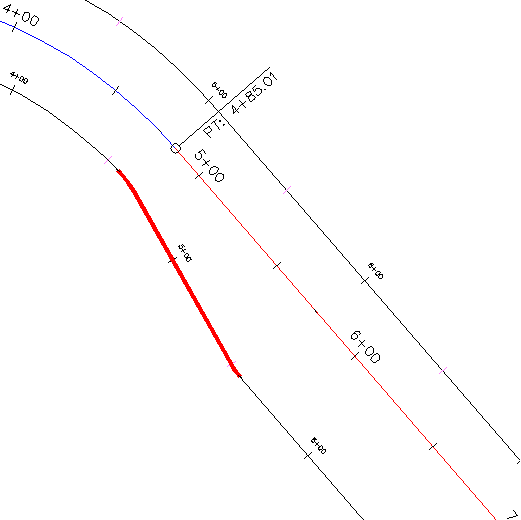
Notice that each region and transition is highlighted in the drawing as you select it.
- Expand the Transition Out category.
- Change the Transition Type from Linear to Curve-Line-Curve.
The transition changes to a line with a curve on either end.

- Under Transition Parameters, for Transition Length, enter 50.
The transition updates to reflect your changes.
Grip edit the widening region
- On the centerline alignment, select the
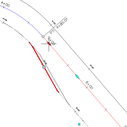
 widening start grip near Station 4+50. The grip turns red.
 - Click to place the grip at Station 5+00.
Notice that when you changed the starting location of the widening, the transition moved with it, while its parameters were maintained.

- On the offset alignment, click the
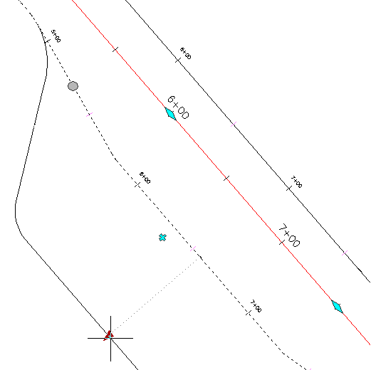
 offset grip. The grip turns red.
 - While the grip is active, enter 50 as the new offset value.
The widening region expands to accommodate the new offset value.
 Note:
Note:The
 grip enables you to add another widening region.
 - Click the
 grip.
grip. The
 grips are now gray, and
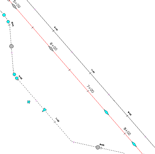
  grips are displayed at the beginning and end of each transition sub-entity. These grips are used to modify the transition geometry.
- Experiment with using the
 grips to change the transition geometry.
 As you grip-edit the transition geometry, notice that the applicable parameter values are automatically updated in the Offset Parameters dialog box.
To continue to the next tutorial, go to Designing an Alignment that Refers to Local Standards.