In this exercise, you specify a center point, the centerlines of the approach roads, and the geometric parameters from which to create a roundabout.
Specify the roundabout center point and approach roads
- Open Roundabout-Create.dwg, which is located in the tutorials drawings folder.
- Click tab
 panel
panel  drop-down
 .
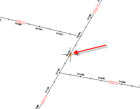
. - To specify the roundabout center point, in the drawing, on the ROAD D alignment, click station 0+140.

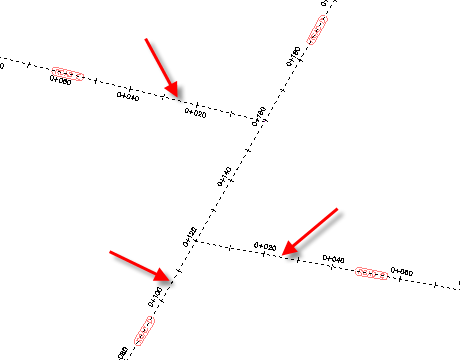
- To specify the approach roads, click Roads C, D, and E as shown. Press Enter.

Specify the circulatory road parameters
- In the Create Roundabout - Circulatory Road dialog box, under Drawing Standard, for Select Roundabout Standard, select US.
- Under Predefined Parameters to Import, select RG = 20. Note:
The Drawing Standard and Predefined Parameters To Import controls enable you to apply preset parameters to a roundabout. You will learn more in Exercise 4: Setting Up Roundabout Design Standards and Presets.
- Under Roundabout Parameters, specify the following parameters: Note:
When you hover the cursor over each control, notice that the applicable portion of the roundabout is highlighted in the preview graphic.
- Outer Radius: 20
- Circulatory Road Width: 8
- Apron Width: 3
- Under Markings Parameters, specify the following parameters:
- Outer Offset: Selected; 0.5
- Inner Offset: Selected; 0.5
- Marker Line Width: 0.3
- Number Of Lanes To Mark: 2
- Lane Marker Line Width: 0.2
- Lane Marker Linetype: DASHED
- Specify the alignment parameters:
- Site: None
- Alignment Style: Roundabout - Circulatory Road
- Alignment Layer: 0
- Alignment Name Prefix: Roundabout
- Alignment Label Set: Roundabout - Circulatory Road
- At the bottom of the dialog box, click Next.
Specify the approach road parameters
- In the Create Roundabout - Approach Roads dialog box, under Predefined Parameters To Import, select RG = 20.
When you change this setting, the Approach Road Parameters section is populated with preset values. You will learn how to modify and save these values for later use in Exercise 4: Setting Up Roundabout Design Standards and Presets.
- Specify the alignment parameters:
- Alignment Style: Roundabout - Approach Road
- Alignment Layer: 0
- Alignment Name Prefix: Approach_WE
- Alignment Label Set: Roundabout - Approach Road
- At the top of the dialog box, click Apply To All.
This action applies the specified parameters to the other approach roads in the roundabout. At the top of the dialog box, you can use either the Previous and Next buttons, or the drop-down list, to examine the parameters of the other approach roads.
- At the bottom of the dialog box, click Next.
Specify the island parameters
- For Predefined Parameters To Import, select RG = 20.
- Click Apply To All.
- At the top of the Create Roundabout - Islands page, in the drop-down list, select South To North Approach.
- Under Splitter Island Parameters, clear the Provide Crosswalk (Length) check box.
At the end of this exercise, you will examine the differences between the South To North Approach road and the others.
- At the bottom of the dialog box, click Next.
Add signs and pavement markings
- Under Signs, in the J5 row, for Leader Length, enter 10.
The Leader Length parameter enables you to place a leader line between the block that represents the top of the sign, and the block that represents the sign.
- In the A25 row, for Distance, enter 60.
The Distance parameter enables you to place some signs a specific distance from the outer edge of the circulatory road. For this exercise, you will place a roundabout sign 60 meters before the driver enters the circulatory road, and a resume sign 50 meters after the driver exits the circulatory road.
- In the AB6 row, for Distance, enter 50.
- Under Pavement Markings, in the Yield Line row, under Linetype, select DASHED.
- Under Crosswalk Markings, clear the following check boxes:
Draw
Break
- Entry
- Exit
- Break At Entry Island Edge
- Break At Exit Island Edge
Note:Do not click Apply to All on this page. Later in this exercise, you will compare the default sign and marking parameters with the values you entered in the preceding steps.
Examine the roundabout components
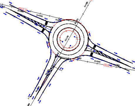
- Click Finish.
The roundabout is displayed in the drawing. Notice that the centerline alignments for the approach roads at Road E and Road C were created with a curve that provides a smooth transition from the parent alignment to the approach road.

Notice that while you selected Road D as an approach road, only one end of it was created as an approach road. When an alignment passes through a roundabout center point, only the alignment end that you click is added as an approach road. You will learn how to add the other end as a separate approach road in Exercise 2: Adding an Approach Road to a Roundabout.
- Zoom in to the South To North Approach road.
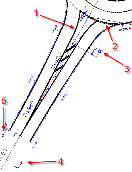
When you compare this approach road to the others, you see that, per the parameters you specified but did not apply to all the approach roads, these elements, which are shown in the following illustration, are different:
- The splitter island is not divided.
- The yield line is dashed.
- The J5 (keep right) sign has a leader line that extends outside the roundabout geometry.
- The A25 (approaching roundabout) sign is 60 meters from the circulatory road edge.
- The AB6 (exiting roundabout) sign is 50 meters from the circulatory road edge.

- In Toolspace, on the Prospector tab, expand the
 Alignments collection.
 The alignments that have a prefix of either Approach or Roundabout were automatically created during this exercise.
To continue this tutorial, go to Exercise 2: Adding an Approach Road to a Roundabout.