In this exercise, you will learn how you can use and customize the Panorama window.
This tutorial continues from Exercise 1: Understanding the Toolspace.
Display object data in the Panorama window
- Use the
 Pan and
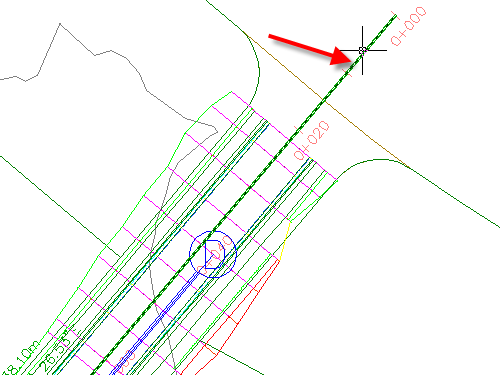
  Zoom controls to locate the beginning of the alignment and pipe network on the far right side of the site.
 - In the drawing, click the green alignment.

- Click tab
 panel
panel 
 .
. - In the Alignment Layout Tools toolbar, click
 .
. A table called Alignment Entities is displayed in a separate window called the Panorama. Notice that the table name appears on a tab. The main control bar is labeled Panorama. Each table in Panorama is called a vista. These tables are useful for editing object attributes. You can edit data in cells that appears as black text. You cannot edit data in cells that are shaded (unavailable). In the next few steps, you will learn to use some of the Panorama controls.
- If the Panorama window covers the alignment, move it by clicking the middle part of the vertical control bar where you see the Panorama title, and then dragging the window to a new location. Tip:
To move the Panorama window, hold down the Ctrl key to prevent the Panorama window from docking when you move it.
- Press Esc to deselect the alignment.
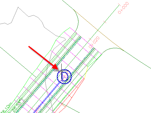
- In the drawing, click the blue structure marker.

- Click tab
 panel
panel 
 .
. - In the Network Layout Tools toolbar, click
 .
. Two additional tables, called Structures and Pipes are displayed in the Panorama window.
- Click the three vista tabs in turn to switch from one table to the other. Bring the Alignment Entities table to the front.
This tutorial uses Intro-1.dwg from the previous tutorial.
Rearrange the columns of a vista
- Scroll to the right until you see the Chord Length column.
- Click the Chord Length column heading, drag the column to the left, and drop it to the right of the Length column.
Notice that each column heading is highlighted as the cursor passes through it. You can rearrange the columns like this to make the table easier to use.
- Right-click the Radius column heading. Click Customize Columns.
The Customize Columns dialog box allows you to modify the appearance of the columns in the current vista. You can hide unnecessary columns by clearing the appropriate check boxes in the Visibility column, or change the width of columns using the Width column. Clicking the New button allows you to save a custom vista configuration for later use.
- Click Cancel to close the Customize Columns dialog box.
Change the appearance of the Panorama window
- On the Panorama control bar, click
 to temporarily close the window.
 - Without clicking, move your pointer over the Panorama control bar.
The window opens while the pointer is on the bar. It closes when you move the pointer off the vista. This is Auto-Hide Mode, indicated by
 . It is useful when you want to periodically consult a table while working in the drawing.
 - Click
 to turn off Auto-Hide Mode.
 - On the Panorama control bar, click
 . Click Transparency.
 - In the Transparency dialog box, move the General slider to a position in the middle of the range. Click OK.
- Drag the Panorama window.
When you move the cursor away from the window, notice that you can see some drawing details through the table.
- In Alignment Layout Tools toolbar, click
 .
. The Pipes and Structures vistas remain open until you click
 in the Network Layout Tools toolbar.
To continue to the next tutorial, go to Tutorial: Using Basic Functionality.