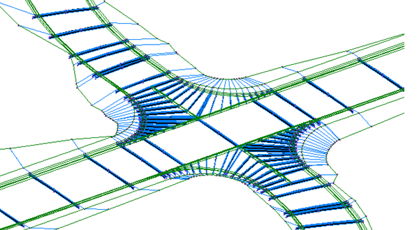
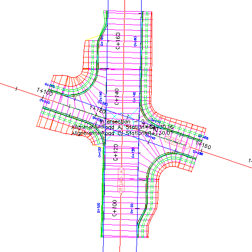
You can create dynamic models of three-way (T-shaped) or four-way intersections.

In its simplest form, an intersection can be created by selecting the location where two alignments intersect. This creates an intersection object (of object type AeccIntersection) in the drawing, and this intersection object is also displayed in the Prospector tree.
Another approach to creating intersections is to first create roadway alignments, offset alignments, and profiles. Once these preliminary design items are in place, you can create an intersection object that utilizes the 3D aspects of these road design geometry components.
Intersections are created from and based on existing AutoCAD Civil 3D objects, which include:
- Alignments (horizontal). Used by an intersection to define the centerlines of the two roads that intersect. Three types of alignments are used in intersections: centerline alignments, offset alignments, and curb return alignments. The centerline and offset alignments are used to define the horizontal geometry aspects of an intersection object.
- Profiles (vertical alignments). Used to define surface and design elevations along a horizontal alignment.
- Surfaces. Used to build surface profiles, and for corridor grading in an intersection.
- Corridors. A corridor can be built automatically to represent the 3D aspects of the intersection. You can also add to this new corridor information to an existing corridor on the intersecting alignment(s).
- Assemblies. Roadway assemblies are required to build a corridor representing the intersection. To build an intersection corridor, you must be able to access appropriate assemblies to build the intersection model. AutoCAD Civil 3D comes with a set of default intersection assemblies that you can use, or you can create your own custom assemblies that have been designed specifically to suit the needs of intersections you create.
- Assembly set. An intersection corridor requires an assembly set, which is a set of assemblies that are designed specifically for a specific type of intersection design. The assemblies included in an assembly set are defined in an .xml file that is referred to as the assembly set file. A default assembly set and assembly set file is included with AutoCAD Civil 3D. You can create an intersection using this default assembly set, or you can create your own custom assembly sets.
- Subassemblies. Subassemblies define the geometry of a corridor section (through an assembly). For example, a typical roadway may be composed of paved lanes on either side of a centerline, a paved shoulder, a gutter and curb, and a roadside grading. These components are defined independently as subassemblies. You can add any type of subassembly to make up a typical assembly, and then apply that assembly for a station range along an alignment.
Intersection objects have their own display style that controls the intersection object marker. Intersection components, such as offset alignments, curb return alignments, and corridors, also each have their own display styles.
