Add floating lines with spirals in situations where you need a spiral transition to a line that is defined by either a pass-through point or length.
To add a floating line with a spiral (from curve, through point)
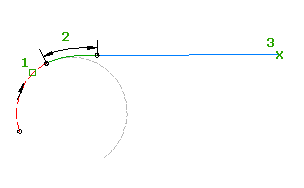
Add a floating spiral-line group, with a specified spiral length and pass-through point, to a curve.
When the attachment entity (1) is edited, the spiral length (2) and pass-through point (3) do not change. The line length and attachment point change to accommodate edits to the attachment curve.

- Click the alignment. Click


 .
. - On the Alignment Layout Tools toolbar, click
 Floating Line With Spiral (From Curve, Through Point).
 The current spiral definition is displayed at the command line.
- Specify the curve end to attach to.
- Specify either the spiral length or the A value, either by entering a numeric value, or selecting two points in the drawing.
Specify a new value, or press Enter to accept the value that is displayed on the command line.
- If the alignment has design criteria applied to it, the minimum value for the current design speed is displayed.
- If the alignment does not have design criteria applied to it, the default value specified in the curve and spiral settings is displayed.
- Specify the pass through point.
To add a floating line with spiral (from curve end, length)
Add a floating spiral-line group, with specified spiral and line lengths, to a curve.
When the attachment entity (1) is edited, the spiral (2) and line (3) lengths do not change. You can adjust or move the attachment curve and the entire spiral-line group moves with it.

- Click the alignment. Click


 .
. - On the Alignment Layout Tools toolbar, click
 Floating Line With Spiral (From Curve End, Length). The current spiral definition is displayed at the command line.
 - Specify the curve end to attach to.
- Specify the spiral length or the A value, by either entering a numeric value or selecting two points.
Specify a new value, or press Enter to accept the value that is displayed on the command line.
- If the alignment has design criteria applied to it, the minimum value for the current design speed is displayed.
- If the alignment does not have design criteria applied to it, the default value specified in the curve and spiral settings is displayed.
- Specify the line length.