Use the plan production tools to quickly create sheets that automatically display station ranges of alignments and profiles in your plans.
Use the Create View Frames and Create Sheets wizards to create sheets that automatically display segments of alignments and profiles in your plans. You can create view frame groups that automatically capture predefined areas along an alignment.
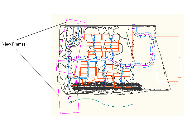
Instead of manually creating many viewports on layouts to show segments of alignments, you can create view frames that automatically capture predefined areas along an alignment. View frames are rectangular areas along an alignment that represent what is displayed in the associated viewports on the layouts (sheets) to be created. This automation saves you from making many manual changes when your design data changes.

View frames represent the alignment data that will be displayed in layout sheets
The plan production tools include the following components:
- Plan Production commands. You can access the plan production commands from the Output tab and Plan Production contextual tab on the ribbon. The Plan Production contextual tab is displayed when you select a view frame or a match line in the drawing.
-
 Create View Frames Wizard. Start the process of using the plan production tools by using this wizard to define a group of view frames along an alignment.
 -
 View Frame Group. The view frame group object helps you manage a single group of view frames that are displaying consecutive station ranges along the same alignment. You can set many options at the view frame group level, such as styles and labeling. View frame group objects are displayed in the Prospector tree, and you can control their default command settings in the Settings tree.
 -
 View Frames. View frames are rectangular-shaped regions along an alignment that define an area that will be displayed in a sheet. The view frame size, shape, and scale comes from a designated viewport that exists on the layout tab of a specified template. After view frames are created, the properties of the view frame objects are saved in the currently open drawing. The view frame objects are displayed in the drawing and in the Prospector tree, and you can control their default style and labeling in the Settings tree.
 -
 Match Lines. In the AutoCAD Civil 3D plan production features, a match line is a straight line that indicate locations in a view frame group where one view frame intersects or matches up with another view frame. Match lines are only displayed in paper space and only in plan view. They are designed to visually indicate the locations (start and end stations) along an alignment where each view frame begins and ends. Match lines have their own object style and they typically include labels that can identify both the previous and next sheet (view frame) along an alignment. You have the option to include a left side match line label, a right side match line label, both, or none, and you can choose where along the match line you want the label to be displayed (top, middle, end of match line). Like view frame objects, match line objects are also displayed in the Prospector tree, and you can control their default style and labeling in the Settings tree.
 -
 Create Sheets Wizard. After you have used the Create View Frames wizard, the next step is to use the Create Sheets wizard to quickly create your sheets.
After you have created view frames and sheets, you can then use the Sheet Set Manager to organize, publish, share, and manage sheet sets.