Discover how Autodesk Simulation DFM can help design a better injection molded plastic part.
-
- Click
 Open, navigate to the tutorial folder and open mouse_upper.ipt. This is typically installed at C:\Program Files\Autodesk\Simulation DFM 2015\tutorial\.
 The model is loaded and the DFM indicators are calculated and displayed in the widget.
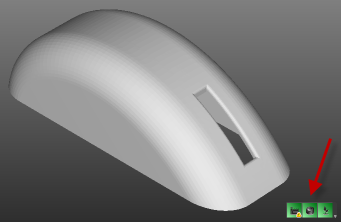 Tip: If the widget is not visible, maximize the window that the model appears in.Three areas of the design are reflected in the widget.
- Manufacturability

- Geometry and production issues that could effect the part feasability.
- Cost efficiency

- The impact of mold, plastic material, and production cycle times on the cost of the part.
- Plastic Material Impact

- The environmental impact of the part. This is primarily based on the plastic material the part is made from.
- Manufacturability
- Click
- Click ().
The elements that are considered when calculating the Manufacturability rating and their relative impact are displayed.
- Hover over the Draft angle icon.
The contribution of the Draft angle component to the overall Manufacturability result is listed.
The contribution is less than 100%, the optimal value and so should be investigated.
- Click on the Draft angle icon, and the areas of the part that are negatively impacting on the part are identified.
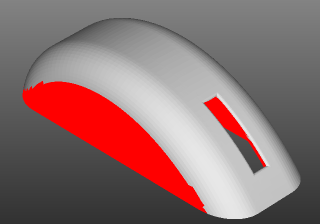
The vertical sides would prevent the easy removal of the part from the mold. The part was modified an the external CAD package. Import the part and review the design.
- Click Open (
 Application menu > Open) and select mouse_upper_with_draft.ipt from the tutorial folder.
 - Click () and click on the Draft angle icon. The problem has been resolved.
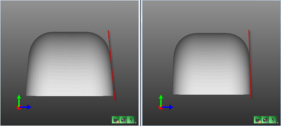
Compare the two models.
- Ensure both models are still loaded and then click
 Tile Vertically ().
 - Click Right on the Viewcube.
- Make the second window active and click Right on the Viewcube.
Addressing manufacturing considerations early in the design process can prevent time consuming rework.