 On the ribbon, click Asset Builder tab
  Author panel Define Connector.
 - Select a planar face, vertex, midpoint, endpoint, hole center, work point, or work plane on the component. The connector point triad appears on the point you select.
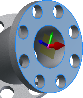
- The red axis on the triad represents the X direction for the object as seen from the plan view (looking down from the top). This is the direction in which the connection is to be made.
- The green axis indicates the side of the connection.
- The blue axis indicates the top, or “up”, side of the connection.
- Optional: To specify a different connector point, click the origin ball of the triad and select a new location.
- Optional: To align the X direction with an existing edge or face, click the red axis on the triad and then select a face or edge to align with.
- Optional: To flip the triad axis, right-click anywhere on the red arrow and select Flip axis from the pop-up context menu. Flipping the triad changes the direction in which the connection is to be made. You can also flip the axis by clicking the red arrow once to highlight it, and then clicking it a second time to change the direction.
- To create the connector point and complete the command, right-click anywhere on the triad or in the graphics window and select OK from the pop-up context menu. The connector point displays as a green sphere.
- Continue to create additional connector points, as necessary.