Overlay DWG files
- Click the New button on the Quick Access toolbar.
- In the New File dialog box, select the appropriate Factory Layout.iam template based on the system of units (inches or millimeters) used in the 2D drawing layout. Click the OK button to close the New File dialog box.
-
 On the ribbon, click
Factory tab
On the ribbon, click
Factory tab
 Layout panel
Add DWG Overlay
to display the Select DWG file dialog box.
Layout panel
Add DWG Overlay
to display the Select DWG file dialog box. - If you are working with Autodesk Vault, then click
 Factory tab
Layout panel
Add DWG Overlay from Vault
. Note: This option is only available when the Vault client is installed.
Factory tab
Layout panel
Add DWG Overlay from Vault
. Note: This option is only available when the Vault client is installed. - Navigate to the folder that contains the DWG file you wish to overlay. Select the file and click the Open button.
- The Layer Settings dialog box displays if the Show Layer Settings dialog on placement check box is enabled in the Factory Options dialog box.
- Additionally, a preview window displaying the drawing appears if the Show Dwg preview in Layer Settings dialog check box is enabled (also from the Factory Options command).
- You can toggle on or off the visibility of any layers defined in the 2D drawing. The drawing preview updates to reflect any changes to layer visibility. Note: Some of the more complex graphical entities from the drawing file, such as xlines, are not supported and may result in a partial display of the DWG overlay.
- The 2D drawing is now overlaid on the factory floor with the 0,0 base origin of the drawing coincident with the 0,0 factory floor origin. The floor resizes automatically to accommodate the size of the drawing overlay.
- The DWG overlay node is represented in the browser with this icon
 . Its name will be identical to the name of the original 2D drawing.
 - Click TOP on the ViewCube at the upper right of the graphics window to obtain a plan (top) view of the factory layout.
- Optional:
 On the ribbon, click
Factory tab
Options panel
Resize Floor
. Use the grips located at the midpoints and corners of the factory floor to dynamically increase or decrease the floor size if applicable.
On the ribbon, click
Factory tab
Options panel
Resize Floor
. Use the grips located at the midpoints and corners of the factory floor to dynamically increase or decrease the floor size if applicable. -
 On the ribbon, click
Factory tab
Options panel
Snap Types
. A drop-down menu displays.
On the ribbon, click
Factory tab
Options panel
Snap Types
. A drop-down menu displays. - Enable the Snap to DWG Overlay check box in the drop-down menu. You can now place 3D factory assets on the designated areas of the 2D layout. Components can be snapped to endpoints, midpoints, and along an entity.
- Use the Align, Reposition, and Set Landing Surface commands in the Relationships panel, if necessary, to help you orient the assets correctly.
Reposition DWG overlays
You can reposition a DWG overlay after placing it onto the factory floor. Using a 3-axis triad, you can move the overlay in the X and/or Y directions. The Z-axis of the triad lets you rotate the overlay into a new orientation. The translations or rotations are performed from the 0, 0 origin of the DWG overlay.
- In the browser, locate the DWG overlay node. Its name will be identical to the name of the original 2D drawing.
- Right-click over the DWG overlay node and select Reposition from the pop-up context menu.
- The Reposition triad appears at the drawing overlay origin. Note: Remember that placing a DWG overlay into a factory floor layout positions the overlay so that its origin and the origin of the factory floor layout are coincident. Moving the overlay in either the X or Y directions shifts the drawing origin away from the factory floor origin.
- Use the triad to move or rotate the DWG overlay. Depending on where you click on the triad, you can make a planar (2D) translation, an axial translation, or an axial rotation.
- On the triad, select the shaft of the X or Y axis (at its base) for linear repositioning of the overlay.
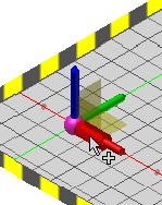
To dynamically reposition the drawing, click and drag the shaft of the axis to move the overlay.
To manually reposition the overlay, click the shaft of the X or Y axis and enter the translation value in the Heads-Up Display. Press Enter to move the overlay and close the HUD.
- On the triad, select the XY plane at the base of the triad for simultaneous X and Y repositioning of the overlay.
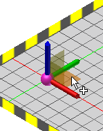
To dynamically reposition the drawing, click and drag the XY plane.
To manually reposition the overlay, click the XY plane once and enter the X translation value in the Heads-Up Display. Next, press TAB to enter the Y value in the display. Finally, press Enter to move the overlay and close the HUD.
- On the triad, select the end of the Z-axis to rotate the overlay.
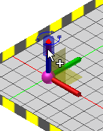
To dynamically rotate the drawing, click and drag the end of the Z-axis to orient the overlay.
To manually rotate the overlay, click the end of the Z-axis and enter the rotation value in the Heads-Up Display. Press Enter to rotate the overlay and close the HUD.
- On the triad, select the shaft of the X or Y axis (at its base) for linear repositioning of the overlay.
- Right-click and select Done to accept the changes and exit the Reposition command. Right-click and select Cancel to exit the command without moving the DWG overlay.
Transform DWG overlays
A DWG overlay can also be repositioned, as well as scaled, using the Transform command. Unlike the Reposition command which moves the overlay relative to the 0,0 origin of the drawing, the Transform command moves the overlay relative to the 0,0 origin of the factory floor.
- In the browser, locate the DWG overlay node. Its name will be identical to the name of the original 2D drawing.
- Right-click over the DWG overlay node and select Transform from the pop-up context menu.
- The Transform dialog box appears.
- In the Offset section, enter a value in the X: text box to move the drawing in the X direction. Enter a value in the Y: text box to move the drawing in the Y direction.
- In the Angle section, enter an angular value to rotate the drawing in the XY plane.
- In the Scale section, enter a value to scale the entire drawing. You can increase or decrease the size of the DWG overlay. The factory floor resizes automatically to accommodate the revised drawing scale. The ability to scale the overlay is particularly useful if you need to convert a metric drawing to imperial units or vice-versa.
- Click the Apply button to preview your changes.
- Click the OK button to accept the changes and close the dialog box. Click Cancel to discard any changes and terminate the command.
Control visibility of DWG layers
Upon initial placement of a DWG overlay, you have the option to toggle on or off the visibility of any layers defined in the 2D drawing. This capability, as well as a drawing preview in the Layer Settings dialog box (if both are enabled using the Factory Options command) updates to reflect any changes you make to layer visibility.
You can return to the Layer Settings dialog box at any time if you wish to change the on/off visibility status of any of the layers.
- In the browser, locate the DWG overlay node. Its name will be identical to the name of the original 2D drawing.
- Right-click over the DWG overlay node and select Layer Settings from the pop-up context menu.
- The Layer Settings dialog box appears with a preview of the drawing, if enabled, and a list of all layers defined in the DWG overlay.
- A checked box to the left of each layer name indicates that the layer is visible in the DWG overlay. Check (or uncheck) the layer boxes to toggle layer visibility on or off in the DWG overlay.
Crop DWG overlays
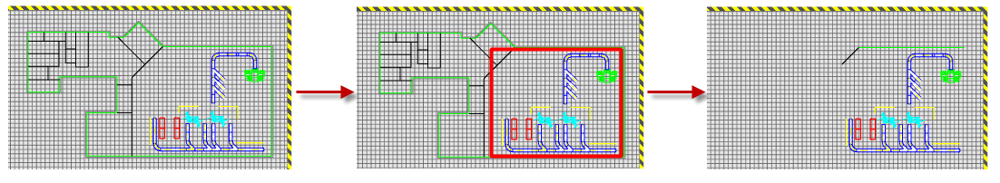
You can trim and remove unwanted portions of a DWG overlay using the Crop Overlay command. Cropping removes unwanted areas of an overlay by retaining only the portion contained within two diagonal corners.
- Start by clicking TOP on the ViewCube at the upper right of the graphics window to obtain a plan (top) view of the overlay.
- In the browser, locate the DWG overlay node. Its name will be identical to the name of the original 2D drawing.
- Right-click over the DWG overlay node and select Crop Overlay from the pop-up context menu.
- A window selection set glyph appears in the graphics window. Pick two diagonal corners that fully enclose the objects you want to include in the cropped area. As you select the corners, the rectangular window appears in red.
- After picking the second diagonal corner, right-click and select Done from the pop-up context menu to create the crop and terminate the command. The portions of the overlay outside the two selected diagonal corners are trimmed away.
Opening an overlay in AutoCAD
There may be occasions when, after placing a DWG overlay into a factory layout, you may want to make some additional revisions to the original DWG file. You can easily launch AutoCAD and open the drawing from within Inventor using the Open Overlay in AutoCAD command. All flavors of AutoCAD, (AutoCAD, AutoCAD Architecture, and AutoCAD Mechanical) are supported.
- In the browser, locate the DWG overlay node. Its name will be identical to the name of the original 2D drawing.
- Right-click over the DWG overlay node and select Open Overlay in AutoCAD from the pop-up context menu.
- The most recently opened flavor of AutoCAD launches and the overlay appears in the AutoCAD graphics window. Make any revisions as required and save the DWG file.
- Return to Inventor. The browser icon for the node will indicate that the original drawing has been revised and the DWG overlay requires an update
 .
. - Use the Update command as described in the Update DWG overlays section (below)
- The original DWG graphics are deleted and the revised DWG file is once again overlaid onto the factory floor.
- Any changes previously made to the drawing X or Y position, angle, or scale are retained in the updated overlay.
Update DWG overlays
There is associativity between the 2D drawing from which the DWG overlay originated and the 3D factory layout. If any revisions occur to the original drawing file, you can read the changes back into Inventor Factory using the Update command.
- In the browser, locate the DWG overlay node. Its name will be identical to the name of the original 2D drawing.
- The browser icon for the node will indicate that the original drawing has been revised and the DWG overlay requires an update .
- Right-click over the DWG overlay node and select Update from the pop-up context menu.
- The original DWG graphics are deleted and the revised DWG file is once again overlaid onto the factory floor.
- Any changes previously made to the drawing X or Y position, angle, or scale are retained in the updated overlay.
Place 3D Inventor Factory assets over 2D AutoCAD Factory assets
If a drawing created using AutoCAD Factory contains 2D Factory assets, 3D Factory assets can be automatically placed over their 2D equivalents using the Auto-place 3D Assets command.
- In the browser, locate the DWG overlay node. Its name will be identical to the name of the original 2D drawing.
- Right-click over the DWG overlay node and select Auto-place 3D Assets from the pop-up context menu.
- The 2D images of the assets in the drawing file are supplemented with their 3D Inventor asset equivalents. The 3D assets are placed in the exact positions and orientations of the AutoCAD 2D assets.
- The original overlay with its 2D Factory assets is retained in the factory layout.
Delete DWG overlays
A drawing overlay may be deleted at anytime.
- In the browser, locate the DWG overlay node. Its name will be identical to the name of the original 2D drawing.
- Right-click over the DWG overlay node and select Delete from the pop-up context menu.
- The drawing overlay is deleted. However, any assets previously snapped to the overlay are retained in the assembly.