You can preselect components before starting the Reposition command, or select them after you start the command. For multiple component preselection, press and hold the Ctrl key as you select two or more objects and then click the Reposition command. It is not necessary to press and hold the Ctrl key when preselecting a single asset.
Repositioning components on the factory floor
You can translate (move) and rotate factory components using the following procedures.
-
 On the ribbon, click
Factory tab
On the ribbon, click
Factory tab
 Relationships panel
Reposition
.
Relationships panel
Reposition
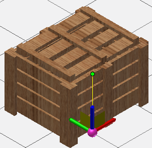
. - Select one or more components you want to reposition. After making your selection, right-click and select Done from the pop-up context menu. A triad appears at the location of your cursor. The triad can be aligned with an edge of a component by snapping the triad to a midpoint or endpoint along the desired edge.
- Use the triad to move or rotate the components. Depending on where you click on the triad, you can make planar (2D) translations, axial translations, or axial rotations.
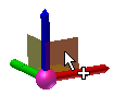 On the Triad, select a plane for 2D repositioning of the component.
 To dynamically reposition the component, click and drag the plane.
To manually reposition the component, click the plane once and enter the translation values in the Heads-Up Display. Left-click or press Enter to move the component and close the HUD.
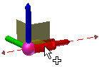 On the Triad, select the shaft of an axis for linear repositioning of the component.
 To dynamically reposition the component, click and drag the shaft of the axis to move the component.
To manually reposition the component, click the shaft of the axis and enter the translation value in the Heads Up Display. Left-click or press Enter to move the component and close the HUD.
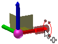 On the Triad, select the end of an axis to rotate the component.
 To dynamically rotate the component, click and drag the end of the axis to rotate the component.
To manually rotate the component, click the end of the axis and enter the angular rotation value in the Heads Up Display. Left-click or press Enter to rotate the component and close the HUD.
Note: By default, angular values are entered in the HUD in Delta mode . That is, the new rotation occurs relative to the current angle of the component. You can also rotate an asset in Absolute mode
  which rotates the asset relative to the rotation angle of the factory floor origin (usually 0 degrees). You can switch between Delta and Absolute modes while rotating a component by right-clicking and unchecking or checking Delta Angle in the pop-up context menu.
- Right-click and select Done to accept the changes and exit the Reposition command. Right-click and select Cancel to exit the Reposition command without moving the components.
Repositioning using snap types
Accurate linear positioning of a factory component along the X, Y, or Z axes can also be obtained using a snap type. All vertex types (point, sketch point, point cloud point, vertex, etc.) are selectable using this method.
To reposition using a snap type, do the following:
- Select the component(s) and place the triad as previously described in this topic.
- Select the X, Y, or Z triad axis that corresponds to the direction in which you wish to move.
- Next, right-click to display the Reposition pop-up context menu. Select Snap To from the menu.
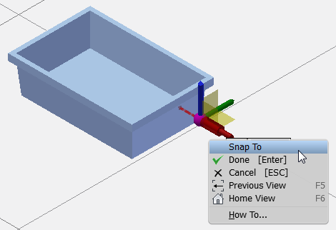
- A glyph featuring a green dot representing the snap origin and a red arrow representing the snap direction of the component replaces the triad.
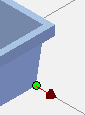
- Hover your mouse over an allowed snap candidate and a preview of the move is displayed. The various snap types are enabled/disabled from the Snap Types drop-down menu on the toolbar.

- Click to reposition the component.
- Right-click and select Done from the context menu to accept the move and exit the Reposition command. Right-click and select Cancel to exit the Reposition command without moving the component.
The Honor Floor option
The Honor Floor option is used in conjunction with the Move Triad option. This option forces the triad down to the floor level, so that the component remains pinned to the floor as it is dragged. The Honor Floor option is enabled by default, but can be disabled using the Reposition command pop-up context menu.
Moving the triad
After selecting one or more components for repositioning, the triad can be located to the precise endpoint or midpoint of a line, or to any point along an edge. When Honor Floor is enabled (the default condition), the triad remains pinned to the floor but is aligned with the point selected.
If you wish to move the triad to a new location, do the following:
- While still in the Reposition command, right-click and select Move Triad from the context menu.
- Select the endpoint or midpoint of a line as the new position for the triad. You can also click at any point along an edge.
- The triad snaps to the location you selected. You can now proceed to reposition components by translation or rotation with the triad in its new position. Tip: Here is a quick method to place the triad when repositioning multiple objects. First, press and hold either the Ctrl or Shift keys as you select one or more objects, and then click the Reposition command. Pick a point on any of the selected components to place the triad. The triad snaps to the location you selected. You can also invoke the Reposition command first, and then select multiple objects.
Rotating and flipping the triad axis
The axes of the triad can be rotated and/or flipped. A vertex, edge, work point, or work axis are all valid objects with which to reorient the rotated triad axes.
- Start the Reposition command and select one or more components. After making your selection, right-click and select Done.
- Right-click the shaft of the axis (X, Y, or Z) you wish to rotate and select Rotate Axis from the pop-up context menu.
- You can move your mouse to dynamically rotate the triad axes, or select a vertex, edge, work point, or work axis to use for axis reorientation.
- If necessary, right-click the shaft of the axis a second time and select Flip Axis to flip the direction of the rotated axis.
- Repeat the process with the other triad axes, if required.
- Once the triad is rotated to your satisfaction, you can proceed to reposition components by translation or rotation with the triad in its new orientation.
Precise component repositioning with trail lines
Trail lines are used in conjunction with the Reposition command to more accurately position factory components. The trail lines also allow you to snap to the virtual intersections of points or vertices.
Use the following procedure to reposition a component from a reference component at a precise distance using a base point on the reference component.
- Begin by enabling the Snap to Vertex or Edge and Snap to Trail Line snap-to options from the Snap Types drop-down menu on the Options panel. Disable the other snap-to options in the menu.
- Start the Reposition command and select the component you wish to move. After making your selection, right-click and select Done.
- Right-click a second time and select Move Triad from the pop-up context menu.
- Select the endpoint or midpoint of a line as the new position for the triad. You can also click at any point along an edge. The triad snaps to the location you selected.
- Next, click the red ball at the juncture of the triad axes. The red ball changes to a green dot. As you move your mouse, the triad moves with the component.
- Move the triad to the precise location for the base point on the reference component. Using your mouse, touch, but DO NOT click the point or vertex you wish to use as the base point from which to move the original component.
- After touching the base point, move the component in a straight line direction from the point. A dashed yellow trail line and value input box appears.
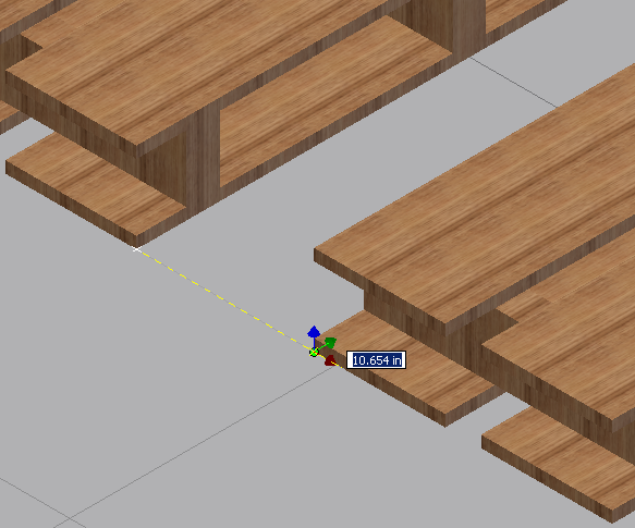
- Dynamically drag the component away from the base point, or enter the distance value directly in the value input box and press Enter.
- The component is now positioned at a precise distance from the reference component.
- Right-click and select Done to accept the move and exit the Reposition command. Right-click and select Cancel to exit the Reposition command without moving the component.