Manually create an asset path
An asset chain path can be created quickly from the AutoCAD command line using a combination of straight lines, arcs, or 90 degree turns. The Arc option is only available for those assets that can follow a curved path. These assets include conveyors, cable trays, electrical conduit, and pipes. The 90 degree Turn option appears for guard rail, hand rail, safety fence, and wall assets. Similar to using the Polyline command, a Close option also lets you close the asset chain back to its start point.
- Begin a new, or open an existing, 2D layout.
- Click Factory tab > Tools panel > Palettes, then click Asset Browser
 from the drop-down menu.
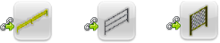
 - Open the System Assets folder, and then open the appropriate subfolder to access chainable conveyors, walls, safety equipment, etc. Note: Chainable assets appear in the asset browser like this:
- To place an asset, click and drag the asset from the browser into the graphics display and release the mouse button.
- The asset has a base point definition and is ready for you to specify that location in the layout.
- Click to place the beginning of the asset chain at the Pick a start point or select polyline [Polyline]: prompt.
- At the Next Point: prompt, enter a numeric value (like 45') or interactively draw the second segment of the asset chain. By default, the segment is drawn as a straight line using the default Line command option.
- If the selected asset can be included in a curved path, the Arc option appears on the command line. Press A on the keyboard to invoke the Arc option to add one or more curved segments to the asset path. Press L to return to drawing straight asset chain segments.
- If the selected asset can be routed into a right-angle turn, the Turn option appears on the command line. Press T on the keyboard to invoke the Turn option to add one or more 90 degree segments to the asset path. Press L to return to drawing straight asset chain segments.
- Continue drawing segments as required. Press C on the keyboard to invoke the Close option if you wish to close the asset chain back to its start point and end the command.
- If not using the Close option, press Enter from the keyboard or right-click and select Enter (or Cancel) from the pop-up context menu when you are finished.
The chainable asset route is now complete.
Using a polyline as an asset path
An existing 2D polyline can be used to define the path for an asset chain. As an example, one polyline could represent walls, a second could define a belt conveyor path, and a third could represent guardrails surrounding the conveyors.
- Begin a new 2D layout and draw one or more polylines that represent asset chain paths.
- Alternatively, open a layout with one or more existing polylines.
- Click Factory tab > Tools panel > Palettes, then click Asset Browser from the drop-down menu.
- Open the System Assets folder, and then open the appropriate subfolder to access chainable conveyors, walls, or safety equipment. Note: Chainable assets appear in the asset browser like this:
- To place an asset, click and drag the asset from the browser into the graphics display and release the mouse button.
- At the Pick a start point or select polyline [Polyline]: prompt, press P from the keyboard to invoke the [Polyline] option.
- You are then prompted to select the polylines to convert into a chainable asset route.
- Select one or more polylines and then press Enter to end the command.
The polyline you selected is highlighted and converted to a chainable asset route.
How to use chained assets in Inventor Factory
Sending a 2D layout with chained assets to Inventor Factory automatically replaces the 2D assets with their 3D equivalents. An associative, bi-directional link called Layout Sync is created between the 2D DWG and the 3D factory floor layout, but the link can later be broken.
There are four different methods you can use to leverage a 2D DWG with chained assets in Inventor Factory.
Method 1: Use the AutoCAD Factory Sync Inventor command. If not already running, Inventor is started; and a new layout is created and automatically populated with 3D chained assets.
Method 2: In Inventor Factory, begin a new layout using the New Layout from DWG command on the Factory Launch panel. When prompted for the file name, specify the 2D DWG containing chainable assets. A new layout is created and automatically populated with 3D chained assets.
Method 3: If a layout is already open in Inventor Factory, use the Create from AutoCAD command on the Suites Workflows panel. As with Method 2, when prompted for the file name, specify the 2D DWG containing chainable assets. A new layout is created and automatically populated with 3D chained assets.
Method 4: In Inventor Factory, begin a new layout using the New Layout command. Then, use the Add DWG Overlay command and specify the 2D DWG containing chainable assets. The DWG is overlaid onto the factory floor and automatically populated with 3D chained assets.
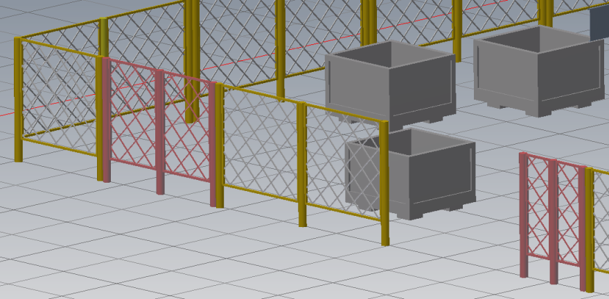
Why do some of the chained assets in Inventor Factory appear in a different color?
Occasionally, non-standard asset lengths are created in the asset chaining process and automatically converted to custom assets. To alert you to this possibility, these custom assets are represented using the color red.