|

The Multi Point Fill command, at its most simplistic level, allows the user to select points on the drawing between which Items will be drawn. This can be likened to using push pins connected with string. Each time a point is selected, Items from the selected library will join it to the previous point.
Starting the Fill
- Start a new drawing.
- Click the Multi Point Fill icon

.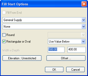
The dialogue displayed controls how the command is to work. The top side controls the Service and Section, the bottom section controls the appearance and position of the drawn item. The following options are available:
- Service - Sets the Active Service to be used
- Section - Sets the Active Section to be used
- Round - Allows the user to select the Round library to be used for the initial fill
- Rectangular or Oval - Allows the user to select the Rectangular or Oval library to be used for the initial fill
- Elevation - Sets the Elevation point for the first Item drawn. The point is taken from the centreline of the duct
- Offset - Allows the user to enter the offset insertion position of the start of the run
A standard Fill
This example will show how to draw Rectangular Ductwork Items however the principle is the same for each library type. Example values are used to demonstrate the process of entering values and the order they are to be entered in.
- Select Duct Extract from the Service type.
- Select Rectangular from the Library Type. Note: The name of the Service is not important for this example only the fact that it contains Rectangular Duct fittings is relevant.
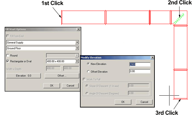
- Enter 2800 into the Elevation box.
- Click in model space to set the first point of the fill. As the mouse is moved away from this point a representation of the items being used in the fill are drawn.
- The process from here is very simple. Click at each point where the fill will change direction. The process can be likened to clicking at each point of a centreline. If the mouse is moved up and down on the Y axis the Item positioned at the last click will be changed to a bend from the corresponding Service library. Once all the points have been placed right click to finish the fill.
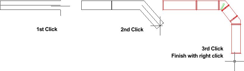
It is also possible to control the fill by using Ortho and Polar angles, typing the distance between the points at the command line.
Changing Sizes and Libraries whilst Filling
It is also possible to change the size of the drawn Items without stopping the fill process.
- Click the Multi Point Fill icon.
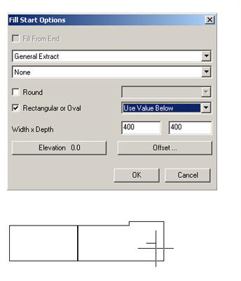
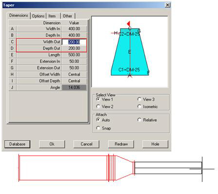
- Click a reducing Item (Taper for example), in the Taper dialogue box enter the new values for Width Out and Depth Out
- Click ok.
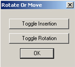
- The Rotate or Move dialogue box should appear, click Ok for now as this facility is not relevant in this case and will be covered later.
- If the Taper / Reducer fitting in the current System is certified then it will be placed on the drawing. If the Taper is not certified its dialogue will be displayed when the mouse is moved off the Multi Point Fill dialogue. Note: If the Taper dialogue is displayed it is not necessary to change any of the end size values as these have already been specified in the Multi Point Fill dialogue. However it is possible to change the length of the fitting from this dialogue.
- Once the Taper has been placed the fill routine resumes as normal.
Using a Fall Gradient
The Fall Gradient can be used to slope the Items as they are drawn. An example of this would be a drainage system. The gradient is entered as the distance travelled for every unit of fall.
- Click the Multi Point Fill icon
. - Select a start point to prompt the Fill Start Options dialogue.
- Select Mains Cold Water Service from the Water & Liquid Supplies Group.
- Select 159 for the size.
- Click Elevation and set the required value.
- Click Ok to the following dialogue boxes to return to the drawing.
- Type e at the command line to return to the Modify Elevation dialogue.
- Check Work To Fall and enter the required gradient.
- Click Ok.
- To finish the gradient two methods are available, via the command line enter the destination coordinates in X, Y, Z or move the cursor in the required direction and enter the distance to travel.
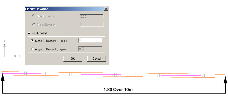
The result will vary depending on the entered units. However a typical result is displayed above. This diagram is viewed in the Y, X plane and show a drop of 1:80 over a 10m distance.