|
When using CADmep one of the fundamental features is the CAD to CAM option. This allows the user to export the CADmep Items within a CAD drawing into CAMduct, thus allowing the manufacture of said items.
The ideal situation is that Drawing Office knows which company will manufacture the ductwork and that both parties work together before any drawings are started, this ensures that the draftsmen are using the same HVAC Database and Ductwork Items that are compatible with the following:
- The Project HVAC Specifications as laid down by the Consultant
- The Ductwork Manufacturers working practices
The key areas to look for are as follows:
- The Specification/Pressure classes have the same names and contain the same size breakpoints
- Establish which fittings, connectors and seams can be used, Establish Throat Radii, correct fitting extensions, etc.
- The CAD/CAM connectors and seams have the same name; this will allow allowances and notching data to be picked up automatically
- Whenever possible connectors & seams are not locked on the fittings this allows the correct connectors to be picked up automatically from the specification
- Rectangular straights have the correct standard lengths, that the folding rules and connector names and connector adjusts are established
- Round duct fittings: are these to be manufactured or purchased from catalogues?
- Insulation data if applicable
Auditing the Manufacturing Files before Manufacturing
It is possible for the drawing office to forward the required manufacturing in the following 3 formats:
- An AutoCAD DWG File: XXX.DWG
This requires the manufacturer to have an ACAD Licence and be proficient with AutoCAD. It is possible the manufacturer could have a requirement to edit the AutoCAD drawing before producing their own manufacturing file.
- A manufacturing file produced by the drawing office; XXX.MAJ - when opened with the manufacturers CAMduct will use the manufacturers own CAMduct database.
- A manufacturing file produced by the drawing office; XXX.ESJ - when opened with the manufacturers CAM-Duct will use the drawing offices CADmep database. This format accurately reflects the ductwork that was drawn and approved. It may not reflect how the manufacturer would wish to make the duct.
Worst Case Scenario
The drawing office has not spent any time understanding how ductwork is manufactured and their main objective is to draw the duct at the correct size and route it through the building. They achieve this goal and the drawing is approved for manufacturing. The drawing office exports a CAM File/Job; XXX.ESJ and forwards it to the manufacturer.
Rectangular Straight duct lengths on the drawing
If the drawing lengths do not reflect the standard lengths produced by the manufacturer the duct runs will not fit. If the straights are made on a coil line and the drawing office uses Ductmate connectors then the standard straight lengths will be 60". If however the manufacturer uses TDC connectors he will manufacture the Straights in 56.5" lengths.
The drawing will need considerable re-working
If this happens the CAD drawing must be edited to use TDC connectors. Because these have different lengths, this will mean deleting all the straights and using the Fill command to add new straights with the correct connectors. If necessary, any small straights can be deleted and the extensions on fittings stretched to fill the gaps. This is the responsibility of the drawing office.
Example: Small ESJ File passed from CAD to Manufacturing
The example below highlights some of the potential problems.
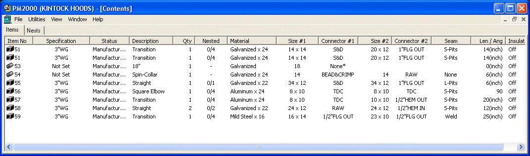
Using CAM-Duct, open the Job and arrange the Job Contents columns as shown above. Remember this uses the drawing offices database, so the specifications, material, connectors, seams and insulation names and allowances are all unconfirmed and may be wrong.
In general the allowances for these and any notching will not be the same as the manufacturer requires.
There may also be a suspicion about the different materials that appear, in this case Aluminium, Mild Steel. The user then needs to determine if this is a CAD mistake and should liaise with the CAD drawing office.
In this case, there may also be a suspicion that a 34" x 12" Straight has an S&D Connector and a 8" x 12" Fittings has TDC.
If the Transition, Tag=57 is edited, it is possible to see that the TDC connector has been locked on the C1 end. For Rectangular duct it is better if fittings are drawn with the connectors unlocked. They are then dynamically applied from the active specification. This allows connectors and seams to be globally changed later by applying a different specification if necessary.
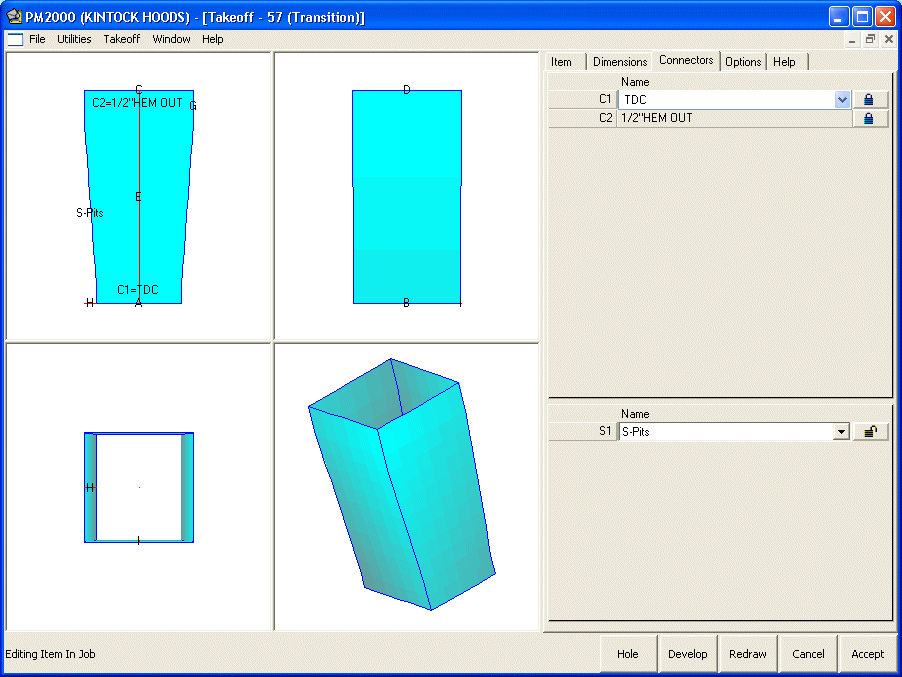
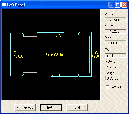
From the development it is also possible to see that the notch is not correct at either end. It should be accepted that the drawing office knows nothing about notches and when we later open the job with the manufacturers database this will be corrected. It is also unlikely the drawing office knows the exact seam allowances, own metal allowances, etc. Before progressing the user should note the exact names of all the specifications, materials, connectors and seams that the drawing office has used.
Tip: Click on the column headings to sort by name. Print the screen. If you do not have the exact names in the manufacturing database these Attributes will be imported and maybe used.
Match by Name Only v Strict Matching
If a job is opened using the manufacturers database (XXX.MAJ), all attributes used by the items will be compared with the entries in the manufacturers database. What happens then is dependent on the Database Reading + Conversion settings in the Configuration Tab found in the Database editor.
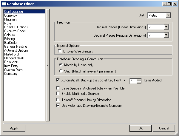
Match by Name Only
If the attribute name matches exactly, associated data will not be imported.
Strict (Match all relevant parameters)
The name and all the associated data will be compared, if there is any difference the attribute will be imported. The imported Attribute name will be appended with the drawing name in brackets.
There are also choices as to where attributes that have the wrong names or data can be corrected. Currently there is no automatic way, our advice is to get the attribute names correct from the outset.
- Save the job as a MAJ File. Go to Files > Save Job as and change the File Type to MAJ and save and close the Job.
- Start a New Job using the manufacturing database.
- Purge the database from Files > Setup > Purge Database. This will eliminate all unused attributes from the database.
- From Files > Setup > Main Database, make sure that the Database Reading + Conversion option is set to Match by Name Only.
- Open the MAJ File previously saved.
At this point the job should be exactly the same as the original ESJ file from the drawing office. If the database is examined however, it is possible to see that new data has been added to materials, specifications, connectors, seams, etc. The new entries will be appended by the Job Name. At this point, if the job were nested this data would be used.
Change Specification Command
The recommended method for quickly making changes is to use the Change Spec command. This allows the user to select a number of Items and replace the specification used by the drawing office by the manufacturers own specification. Obviously, the user must establish that the new specification meets the project requirements.
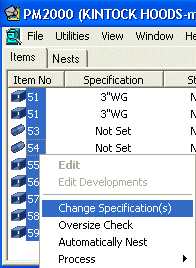
Important Note: Items passed from CAD to CAM have stored with them the developments associated with the CAD attributes and pattern options. Select all Items and Right Click choosing Change Specification(s) > Click OK. This is a quick method to ensure that the items are re-developed and use the attributes associated with the current specification assigned to each Item. Editing each Item separately has the same affect. Remember if the original specification name assigned to each item matches the specification name in the database, the data will be used, however locked connectors or seams will not be changed.

- The New 3"WG Specification calls for the same connector, i.e. TDC or S&D.
- The connector was locked on the original Item.
At this point it is also possible to change to a new specification on any selected items provided they are set to use the same material.
Try Editing a few of the items and check the developments. In particular check any notching. Imported connectors will probably not have the correct metal allowance or notch assigned. The user may also wish to change the connector if it was originally locked.
Feed back changes to the Drawing Office
If it is likely that drawings will be continuously received from the same source then it is better to ensure they are using the same specifications, materials and connector/seam names. The drawing office should also edit their fittings so that connectors are not locked on Items unless this is absolutely necessary. The user can then confidently use the Change Spec command to ensure you are using their own allowances and notches.