|
The command allows the user to convert 3rd party 3D models into MAP *.ITM files for future use within any of MAP software modules. The process gives the user the benefit of being able to use the model for collision detection, assigning attributes e.g. specification, weight, price etc and the ability to connect the correct size pipe, duct or cable tray. Inserting a predefined block called "CONNDEF" enables the user to define attachment points for the final converted model, a set of attributes can be assigned values that relate to width, depth and type of connection point to be added.
Any additional End Point snaps may also be included, see Adding custom Snap Points towards the end of this topic.
Procedure
Creating the CONNDEF block
- Create the geometry for the block (see below for recommended solution).
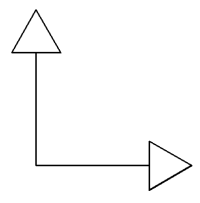
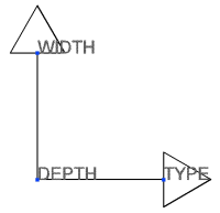
- Type ATTDEF at the command line in AutoCAD, add the following attributes to the geometry WIDTH, DEPTH & TYPE. Note: The attributes must be positioned on the block correctly, the positions will determine the directional vector when the CadDuct ATTACHER arrow is positioned on the converted model (see image below for guidelines).
- Save the geometry & attributes to block called CONNDEF.
Executing the CONVERT3DMODEL command
- Open the 3D model in AutoCAD.
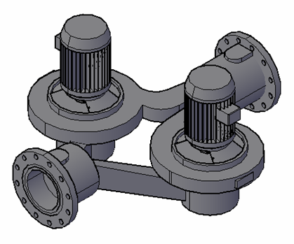
- Determine the size of and types of the connection points.
- Insert the "CONNDEF" block at the desired connection points on the model and (see image below for correct alignment).

- When prompted for the attribute values, insert the correct dimensions for WIDTH, DEPTH and either ROUND, RECTANGULAR or OVAL for the connection TYPE. Note: Custom snap points custom snap points can be added at any time.
- Type CONVERT3DMODEL at the command line in AutoCAD, when prompted to select the model to convert.
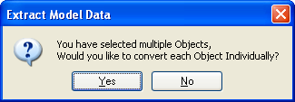
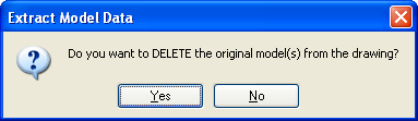
- If the model is made up of more than one 3D solid, the following prompt will be displayed giving the option to convert each item individually.
- The next prompt enables the original model to be deleted during the conversion.
- Once the model has been converted to a CadDuct item, executing the command SAVETOFOLDER allows the item to be saved into the ITEM FOLDERS for future use (see item dialog below from converted model).

Adding custom Snap Points (Endpoint)
Converted models only have node snap connection points as defined by the CONNDEF blocks, additional snaps at other locations about the model may be needed, the following outlines how to include any addition endpoint snaps.
Creating the SnapPoint block
- Start a new drawing and create the geometry for the block at 0,0,0.
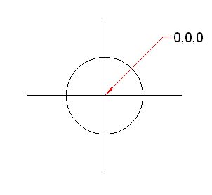
- Save the drawing to a location, call the drawing filename "SnapPoint".
- Use the INSERT command, browse to the SnapPoint drawing. Note: The Insert dialog should be using the drawing Name, verify the block name is "SnapPoint" otherwise additional snaps will NOT be created.
- Add as many SnapPoint blocks to the model geometry as necessary.
During the Convert3Dmodel command process, all SnapPoint blocks will be converted to endpoint snaps.