This article shows how Autodesk Fabrication Software can provide a complete workflow and is able to track products from the Drawing Office or Order Processing through to Manufacturing and Delivery.
Workflow explained
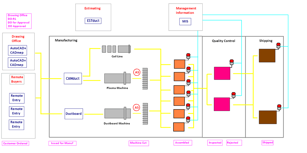
The diagram shows a typical factory layout for manufacturing both Metal and Insulated board ductwork. If Round duct is applicable here the a Tube former would be added in the process.
Typically the main CNC machines used for manufacturing are:
- A coil line for manufacturing straight duct.
- A plasma profiling machine to cut metal fittings.
- A Routing machine that uses either Routing tools or Tangential knives for cutting insulated board (Ductboard).
The input of jobs for the manufacturing department can originate from:
- Remote Agents, Customers, Site Operatives using our Remote Entry software
- Automatically from the Drawing Offices using CADmep.
- Takeoff from approved paper drawings through our CAMduct or Ductboard software.
Estimating could also be involved in this process for the costing side using our ESTduct program.
Ductwork for several projects maybe processed simultaneously and it can be difficult knowing exactly the percentage complete for each project. It is important to have a complete audit trail of the items passing through each system. This can be archived by using the concept of Item Statuses, Bar Coded labels for parts being produced and then Status checking.