|

The Sectional View command is designed to aid the construction of Section. This is accomplished using AutoCAD clipping planes. Only one clipping plane can exist per viewport.
At its basic level a Clipping Plane works like two opaque parallel sheets that are inserted into a drawing. Only Items between these sheets are visible, all other Items are hidden. To define those sheets it is necessary to define two points on the drawing.
- Create a drawing similar to the example below. In the example the Sectional view is needed to reveal the blue Items from behind the red.
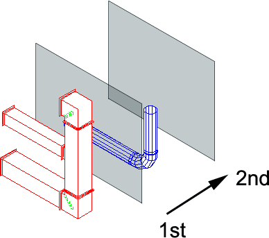
- Because it is necessary to select a point between the red and blue Items the drawing will need to be rotated. This can be done using the standard AutoCAD® view commands.
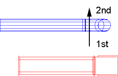
- Click the Create Sectional View icon. It is now necessary to specify the two points which make up the clipping planes. The points used for this example are sown in the diagram below.
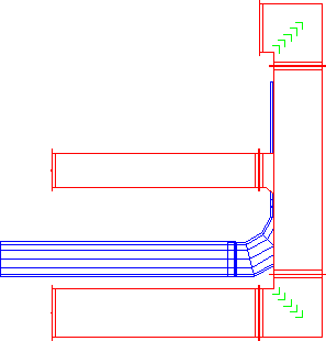
- The viewport will now change to display the Items between the clipped planes.
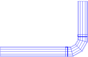 Note: If the Items to be clipped are perpendicular to the selected viewport and contain connectors, it is advised that the clipping plane is created to enclose the connector detail. i.e. If the plane cutting through a Rectangular Straight is in between the connectors they will not be visible.