Description: To provide an understanding on the drawing commands within the 3D Viewer
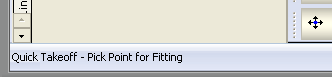
When using the commands that are listed below. It is always best practise to view what is displayed in the status area of the software. This is located towards the bottom left of your view when in the 3D Viewer. This helps you understand what is expected of you when running a command.
Here is a breakdown of all the commands and a description as to what each one can achieve by selection.
ADDAREA (AREA):
ADDCAMERA (ACAM): This enables the user to add a custom camera view which can be used to display different views in a Worksheet.
ADDCOGMARKER (COG)
ADDELINK (AEL): This adds a link top external data.
ADDLAYOUT (ALO): Enables you to create additional viewports that can be selected via tabs along the bottom of your screen. Typing this command into the 3D Viewer prompts the user to name the additional viewport that will be created. The Global tab is the combined "Master" view from the various tabs that are created. Underlay's only need to be imported once on the Global tab - You can then right click on the Global tab and identify which views you want this displaying inside.
ADDMARKER (AMK): Enables the user to place a Marker in the 3D viewer space. This is used if the user need a snap point in a space where there is not anything to snap to.
ADDMSLAYOUT: Enables the user to create a new Multi Service layout
ADDSELSET (ASS): Creates a new Selection Set
ADDTEXT (TXT): Prompts the user to add Free entry text within the 3D viewer. Users can specify the height of the text to be inserted once actual text has been confirmed. Text styles can also be applied to the text.
ADDUNDERLAY (AUNDER): Prompts the user to import an underlay (DXF, DWF file types for example). This is identical to using the Right Click > Import Underlay option.
ALIGN (AL): Allows the user to rotate an object to a specific alignment
ALIGNSCALE (AS): After importing an object, this command allows the user to specify the alignment and to what scale the object is to be re-adjusted to.
ATTRIB (ATTR): Displays the objects Attribute dialogue, details include Description, Weight, Area, Material etc BODTOD : Displays the geographical reference to the Top of Duct and the Bottom of Duct on the selected items. CALCDUCT (DUCTCALC): Brings up the Duct Air Flow Calculator similar to the option on the toolbar.
CHANGELAYOUT (CLO): Allows the user to go to the Layout named when prompted.
CHANGESPEC (SP): CHANNSZ (CAS): Allows the changing of your text size. You can set the value of your displayed text in the view. Selecting this command allows you to multiple select text within your drawing via dragging a selection window. You are then prompted with a value box to insert your new size.
CHECK (CHK): Carries out a check of the Drawing and looks for Conflicts or clashes in the Drawing, also checks for Connectors that aren't connected to other Connectors properly.
CHECKCONN (CNN): Checks the Drawing for any Open Ends
CHECKDUP (CDP): Scans the Drawing for Duplicate Items.
CLEARSPOOLS (CSPL): recommend COPY (C): Copies the selected object(s)
COPYCLIP (CPY): Copies the Selected Object to the Clipboard to allow Pasting at a later time.
CREATESPOOLS (RSPL):
CUTCLIP (CUT): Cuts the Selected Object out of the Drawing and places it in the Clipboard for Pasting later.
DEFANNSZ (DAS): Sets the default annotation size.
DEFAULTUCS (DEFUCS)
DEFINESPOOLS (DSPL):
DELCAMERA (DCAM): Opens a Dialogue box listing the Current Camera Views available in the Drawing, the selected Camera can then be Deleted out of the Drawing.
DELETE (DEL): Deletes the selected object(s)
DELLAYOUT (DLO): Deletes the Active Layout Tab
DELSELSET (DSS)
DIGISCALE (DIS):
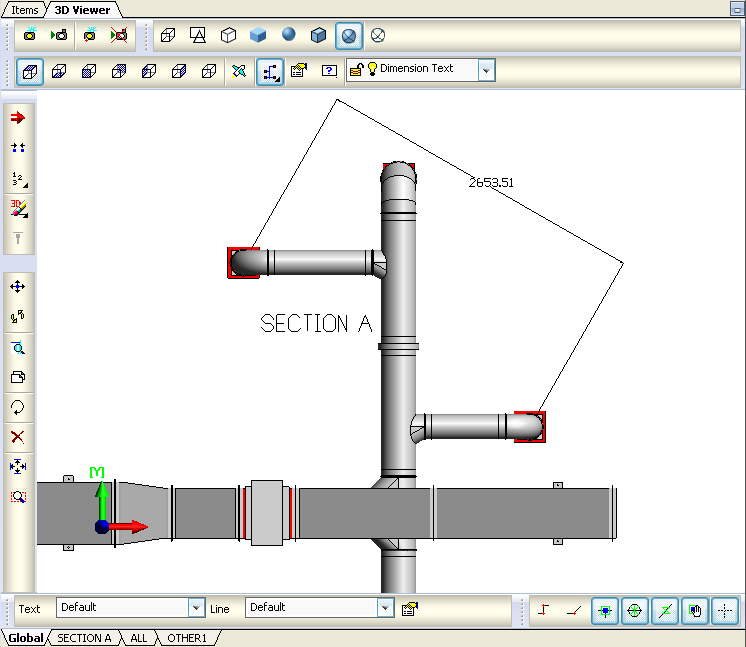
DIMALIGNED (DAL): Creates an alignment between two points. Selecting this option will allow for you to manually select points on your view that are required for measuring - hovering over objects will allow to snap to your desired point. You can then present dimensions on your tender drawing as shown below which do not necessarily need to be parallel.
DIMANGULAR (DAN)
DIMDIAMETER (DAI)
DIMLABEL (DLB)
DIMLINEAR (DLN)
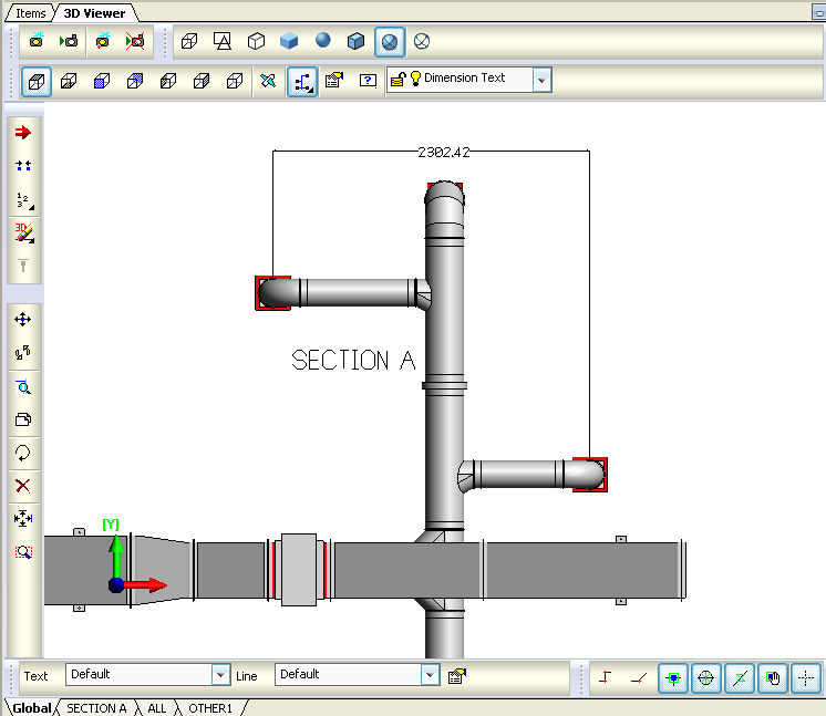
DIMORDINATE (DOR): Creates the dimensions but in a parallel mode only for straights unlike the angled version when using the DAL command. See below:
DIMRADIAL (DRD)
DUCTSIZE : This command can be used to highlight on screen the dimensions of you duct. Selecting an item whilst within this command creates an annotation of the items end size.
DWGEXPORT (DWGE)
EDIT (E): Using this command allows for the editing of a selected object.
EDITCON (MANC): Shortcut to the Constraints Manager interface.
ENDRUN (ER): Whilst in Design line mode and creating your run, using this command will end the run similar to a Right Click.
ERASE3DITEMS (E3D):
FILL2ENDS (F2E): Performs a fill between 2 ends.
FLEXFILL (FF):
FLY: Enters the Fly Mode similar to that on the toolbar. Using this command allows for the fly mode to be user controlled. Left clicking and holding will determine the speed in which you navigate forward. . Right clicking and holding will determine the speed in which you zoom out backwards. The direction of movement is determined by mouse movement. GLIDE (GLI):
GOTOITEMS (GI): Allows the user to select an item from within the viewer and this will change the view to the Job Contents screen with the selected item in view. Useful if using a fairly large drawing and you want to single out an item.
HELP (?): This command brings up the Command List which includes commands that are available.
HIDE (H): Hides the Selected Items from the current Viewport.
HIDEMARKERS (HMK): Hides the Markers created when Check is run or when a User Defined Marker is placed on the Drawing. The user will be prompted to select the Marker Type that is wanting to be hidden. These are ALL, CONFLICT, OPENEND, DUP, and USER
IFCATTR (IFA)
IFCEXPORT (IFCE) is a Data Model format to facilitate interoperability in the building industry.
ISOLATE (I): Lets the user select Objects in the Drawing to display while it Hides the rest.
ISOLATENEAR (IN)
ITEMDETAILS (ITMD)
ITEMNO: Shows Item Numbers on the selected Items in a Drawing.
ITEMPROP (IP): This command will bring up the selected objects Item Properties window as shown below:
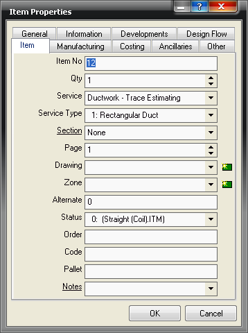
This makes it effortless for accessing a particular item and its properties rather than searching for that specific item in Job Contents. Changes can be made in the normal way using this Properties window. JOINITEMS (JI): Joins selected objects together.
LAYOUTMANAGER (LM):
LOCATEGUID (LG):
M3DEXPORT (M3DE): Exports the Drawing in MAP Proxy Graphics format.
MAKESUB (MS): Converts the selected Objects into a Sub-Assembly.
MOVE (M): Moves a selected item via a node. Using snap to node can allow the item to be snapped up against other items.
MSLCLEAR: (MSC) Clears Multi Service Line Dirty-Flags.
MLSSHOWSERVE: (MSS)
MLSTRACEPATH: (MTP)
MULTISERVICEFILL: (MSF)
NAVIGATE (NAV):
NEWDESIGNOBJECT (NDESOBJ): Creates a New Design Line entry.
NEWMSLOBJECT (NMSLOBJ):
NODESTRETCH (NSTR): Allows the user to Drag multiple Node Points
OFFSETLINE (OL): Allows the user to Offset a selected Design Line
ORBIT (O): Creates central pivot point for you then to orbit around the design using your mouse.
PASTECLIP (PST): Allows the user to Paste an Item previously saved to the Clipboard using COPYCLIP or CUTCLIP
PRDROPS (PDS)
PRINT (PRN): Sends the current View to the Printer, this will be in the layout defined using WORKSHEET
PROCESSRUN (PROCESSRUN)
REGEN (RG): Regenerates all objects in view. Useful if changes have been made to the drawing and a refresh is required.
REMELINK (REL)
RENCAMERA (RCAM)
RENUMBER (RN)
RESTORECAM (RCAM)
REVDEDIGN (REVD): Creates a design line from a drawn and selected object and calculates width and depth in the process. Prompts for the selection of the item in which to create the design line from.
ROTA (RA): Enables you to select the object(s) and insert a value to be rotated by in degrees. Clicking on the object brings an input box to insert your value.
ROTATE (R): Enables you to select a pivot point to then rotate your object(s). Again this can be used for multiple part rotation by selecting each object before using the command. This method of rotation will use the snap points to rotate the object(s)
ROTATEATEND (RAE): Enables you to select the end of an object and insert a value for that object to be rotated by in degrees. Clicking on the end of the object brings an input box to insert your value.
ROTX (RX): Rotate object(s) along the X axis. You can multiple select objects and rotate them all in one instance.
ROTY (RY): Rotate object(s) along the Y axis. You can multiple select objects and rotate them all in one instance.
ROTZ (RZ): Rotate object(s) along the Z axis. You can multiple select objects and rotate them all together.
SECNSIZE (SIZESECN): Accesses the Section Flows dialogue box.
SELECTALL (SELA): Selects all Items in the Drawing
SELECTINV (SELI): Changes the Selected Items to Unselected and vice versa
SELECTNONE (SELN): All selected Items will be deselected.
SELLAYER (SL):
SELRUN (SR): Selects all Objects connected in a run to the Selected Object.
SELSERVICE (SS): Selects all Objects that share the same Service as the selected Object.
SELSET (SEL)
SETATTACHER (A): Positions the arrow for where the next object will be placed and in which direction. Clicking on the ends of the object(s) allows the attacher to be placed and multiple clicking will position the direction.
SETCONSTRAINT (CONST): Must be in Design Line mode for use of this command. Restores Design Line sizes and elevations so they can be drawn again and saves having to re-enter them. On running the command it prompts which line you want to copy the constraint for.
SETELEVATION (ELEV): Sets the elevation of the selected object. This command when activated prompts you for the elevation height of the object.
SETSCALE (SS): Allows the user to set the Scale of the Underlay.
SETTINGS: Opens up the 3d Viewer Settings window.
SETUCS (SUCS):
SETZ (SETZ)
SHADED
SOLID
SOLIDLINES
STORECAM (SCAM)
STYLES: Opens a Dialogue box to allow the user to change the current Line Style and Text Style in the drawing.
TRANSPARENT:
TRIMBLEEXPORT (TRIME):
UCS (UCS):
UNDO (U): If wanted to go back to a previous state the undo command will go back to an earlier time in your drawing.
UNHIDEEALL (UHA)
USETSCALE (USS)
VIEW1 : Displays a Top View (Plan) of the Drawing
VIEW2: Displays the drawing as seen from the Bottom
VIEW3: Displays the drawing as seen from the Front
VIEW4: Displays the drawing as seen from the Back
VIEW5: Displays the drawing as seen from the Left
VIEW6: Displays the drawing as seen from the Right
VIEW7: Displays the drawing as seen in a SW Isometric Angle
VIEW8: Displays the drawing as seen in a SE Isometric Angle
VIEW9: Displays the drawing as seen in a NE Isometric Angle
VIEW10: Displays the drawing as seen in a NW Isometric Angle
WALK (WLK)
WIREFRAME2D: Displays the drawing as a 2 Dimensional Wireframe Drawing
WIREFRAME: Displays the Drawing showing all edges.
WIREFRAMEHLR: Displays the Drawing as a Wireframe but hides the lines that would not be shown if displayed as a Solid.
WORKSHEET (WSHT): Opens the Worksheet Editor for Printing the Display. Pre-created Worksheets can be selected here for Printing or a new Worksheet can be created.
ZONEADDEXCLUSION (ZAX)
ZONEALIGNCEILING (ZAC)
ZONEAPPROXIMATEARC (ZAA)
ZONECEILINGITEMALIGN (ZCIA)
ZONECEILINGPAINT (ZCP)
ZONECLEARCEILING (ZCC)
ZONEDELETEEXCLUSION (ZDX)
ZONEDELPOINT (ZDP)
ZONEDELPOINTRANGE (ZDPR)
ZONEEXPORTSIL (ZES)
ZONEFILLCEILING (ZFC)
ZINEINSPOINT (ZIP)
ZONEOBJBROWSER (ZOB)
ZOOMTOFIT (ZF): Re-creates your view so your drawing fits within the on-screen 3D Viewer window as a whole image.
ZOOMTOWINDOW (ZW): Allows selecting an area of your drawing using two points with the mouse click. The software then magnifies the drawing and displays only the selected region in your view.