The Segment Bend is a commonly used circular fitting, it is therefore essential that the user is aware of the different options available and how they are used. The following information will attempt to explain these options as well as give other relevant information to the Segmented Bend Pattern.
Options tab
When the dimensions of the segmented bend have been entered, it is then necessary to set the following options accordingly.
Number Of Segments
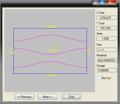
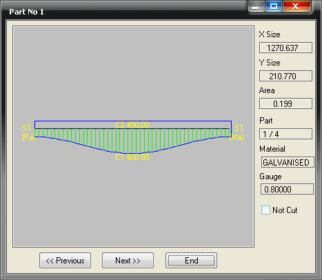
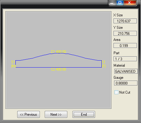
This option allows the user to enter the amount of segments that the bend will be made in. The amount entered will be the amount of actual parts used. Therefore the example above, which is set to 4 will produce 2 end pieces and 2 full segments.
Seam Position
The value entered here will determine where the seam will placed. Any amount between 0 and 360 degrees can be entered here.
- If Zero degrees is entered, and the bend has an even amount of segments the seam will be placed in the throat. If the bend has an even amount of parts, the seam will be placed in the throat on the first segment of the bend, which will then put the seam on the heel of the last segment of the bend.
- If 90 degrees is entered the seam will be at the bottom.
- Entering 180 as the value will have the opposite effect as entering Zero.
- If 270 degrees is entered it will have the opposite effect as entering 90 degrees.
Cross Break
The option allows the user to determine the number of times the development will be broken into equal parts across the segments. This can be used together with the Nest Break option to fine-tune the breakdown of the development.
Single Segments
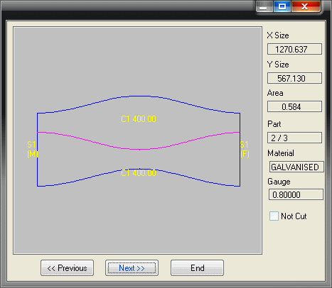
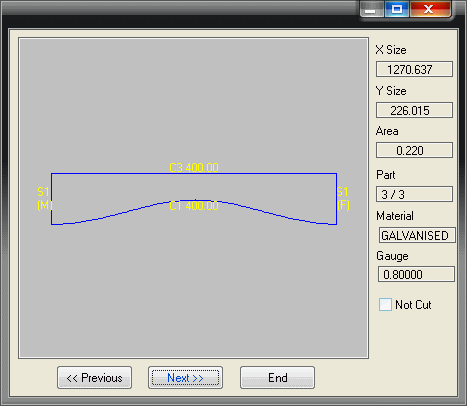
The Single Segments option determines whether the segments of a bend will be cut in a block or as single segments. The two images below show the developments of the same bend. The image on the left shows the developments of the bend with the Single Segments option set to No. The image on the right shows the developments with the Single Segments option set to Yes.
Note: If the bend is to be made in single segments, the seam will be in the same place on all of the segments. Otherwise the seams will be alternated.
Diameter Type
This option sets the diameter type of the fitting. The options are Nominal, Inside or Outside.
Automatic Nest Break If Oversize
If Yes is selected, the software will automatically calculate the required nest break automatically when the development is too large too fit on the sheet. This will be sliced along the development line of the relevant segment. If No is selected the part should be sliced using the Nest Break Start Segment & Nest Break End Segment options.
Notch Angle For Seam
This option only applies only when the Single Segment option is set to No, and adds a vee notch at the edges of the segments to form a slope through the seam allowance.
Nest Break Start Segment and Nest Break End Segment
This option allows the user to break the development of a bend along the development line of 1 or 2 of the segments. The location of the break can be determined by entering the segment number where the break will start. The segment numbers can be determined as follows.
The bend above has been made in 4 pieces. Segments are numbered from the bottom upwards. So in this case it would be Segment 1 at the bottom and Segment 2 at the top. Once this is determined it is easy to break the nest in the desired place. For example, it is possible to break the development above to produce the middle segments (2 & 3) together, and the end segments separately. This is particularly useful when the development is to big for the sheet.
- In the Nest Break Start Segment field type 2
- In the Nest Break End Segment field enter 3 and click on the Develop button and the development will be split as follows.
Marker Type
There are three different options here. None, Notch and Slit. If Notch or Slit are selected an alignment notch will be placed exactly opposite the seam.
- If None is selected no alignment notches will be applied.
- Select Notch to apply an angled vee notch will be applied. The configuration of which is determined in the Pattern Options.
- If Slit is selected, a straight up and down slit will be applied. The depth of the slit is the same as the Notch mentioned in the previous step.
Diameter Reduction
This option allows the user to enter an amount that will be used as a small reduction value to be applied to one end of the bend, primarily for converting between Outside and Inside diameters.
Marker Depth
The depth of the marker notch can be altered here by entering a depth. If the Default option is chosen the depth of the notch/slit will be determined as in the Marker Type section above.
Mark Sides
If the user selects No, alignment notches will be applied only to the heel and throat of the bend. If Yes is chosen, alignment notches will be applied to the heel, throat, top and bottom of the bend.
Leg Length
This option controls whether the bend radius (inner or centre) is entered or calculated from entered centreline leg lengths.
- If No is selected, the bend radius is entered.
- Select Yes and the bend leg lengths are entered excluding the extensions.
- If Length Includes Extensions is selected, the bend leg lengths are entered including the extensions.
Fixing Holes On Extensions
This option is normally only used when then bend is being produced for lagging. If fixing holes are used to form the developments, this option controls whether the holes are allowed to be placed in the straight extensions. This is to allow the bend to slip into a straight duct without the screws getting in the way. Select Yes or No as appropriate.