|
Provides a simple and affective way of joining two Items of duct or pipe that are distances apart. The command prompts the selection of duct/pipe ends to be joined, then presents the user with possible solutions for joining the Items, including the totals for Weight, Area, Installations Time and Cost for each solution.
The Fill Between 2 Ends command uses the Items available from the currently selected service. They should be certified to prevent the user being prompted for sizes etc. If the Items are not certified the user must click OK to each item's Edit dialog.
When using the Fill, Items are automatically sourced in the order they are displayed. If there are two bend Items i.e. Radius and Mitred, the first Item in the Service is used. There is the option to exclude any of the Service Items from the Fill, refer to the Exclude from Fill option.
For 2.41 or latest versions, the Fill Between 2 Ends button  initially prompts which method to use:
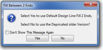
Click No to use the older Fill Between 2 Ends.
Toolbars & Fly-out menus
 Change Views
 Fly Mode
 Glide Mode
 Walk Mode
 Navigate Mode
 Show Items
 Show UCS Axis
 Show Design Lines
 Show Underlays
 Show Proxy Graphics
 Show Dimensions
 Show Zones
 Clipping Planes
 List All Commands
 Styles
 Rotate View
 Viewer In Viewer
 Zoom To Fit
 Zoom To Selected Region
 Store Camera
 Retrieve Camera
Fill Examples
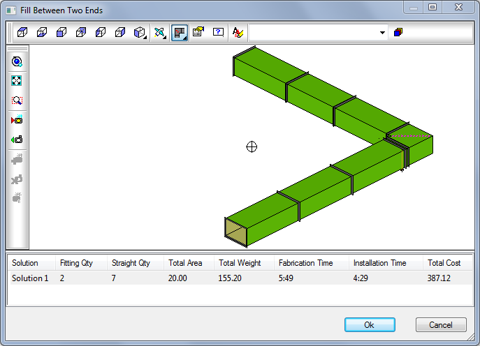
Duct/Pipe - Items positioned 90o to each other on the XY Plane, there is difference in the Z height between the connector nodes and the end sizes are the same. Other angles are supported, but this depends on the Service selected and the available products.
The number of solutions provided can be affected by the distances between the open ends, shorter distances may not allow the placement of all available fittings. E.g., if the fill routine to consider placing 60o bends rather than 90o, the distance between open ends may need to be increased.
Electrical - Ends are parallel to to each other on the XY Plane, there is a difference in the Z height between the connector nodes and the end sizes are the same.
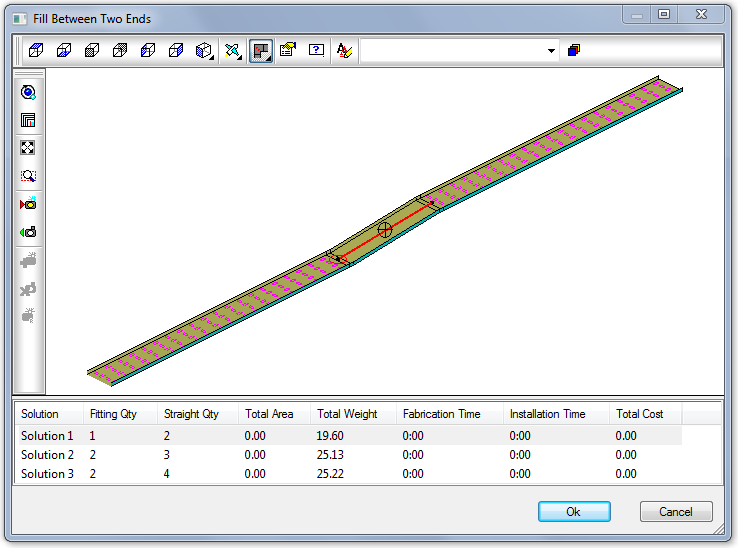
Single Fittings - Ends are parallel to each other on the XY Plane: there is a difference in the Z height between the connector nodes and the duct end sizes are different: a transition is required and will be offsetting in 2 directions.
