Utilising the Sub assembly function to combine a "Transfer grille with a top entry plenum box" into a single dynamic item
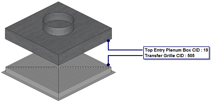
- Plan the required items to be combined as a dynamic sub assembly. Illustrated below a generic example of a "Transfer Grille", with a "Top Entry Plenum Box". To insert the items into the model, Select within the active Service Template or folder structure , then position individually within the model accordingly.
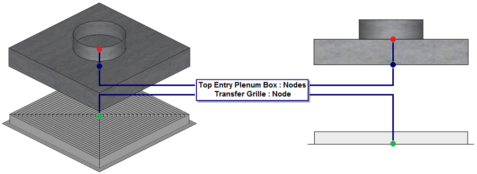
- With the items present in the model, consider the position and orientation of the items. Rotating and snapping to ensure they are in relationship of each other, as you would expect when utilising for co-ordination. Each individual item has a distinctive node insertion point present. See illustration below:
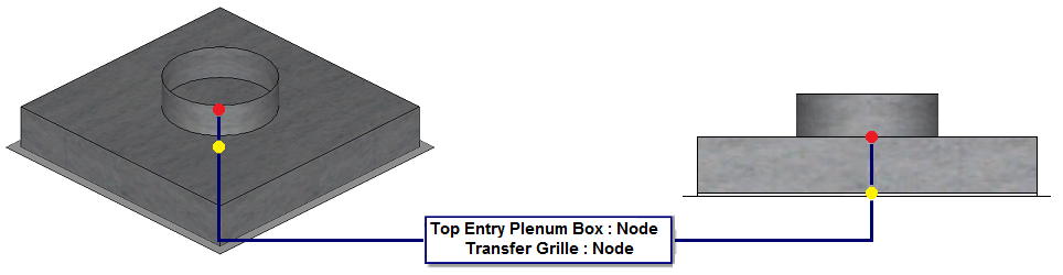
- By Moving, Rotating & snapping, the "Top Entry Plenum Box" until the "Blue" node is in relationship with the "Transfer Grille" Green node. As illustrated:
- With the items in the correct location & orientation in relationship with other, Type SAVEASSUBASSEMBLY. Select the "Transfer Grille" & the "Top Entry Plenum Box".
- Automatically, the Save Item to folder dialog will be prompted, Name and save to an appropriate location within the folder structure. Select OK, to finalise the command.
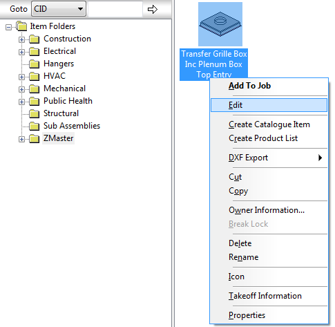
- To edit and customise, Type FOLDERS. Locate the appropriate sub assembly previously saved.
- Right click on the Sub Assembly >> Select >> EDIT.
- Automatically, the "Edit Sub Assembly" dialog will appear for the appropriate sub assembly.
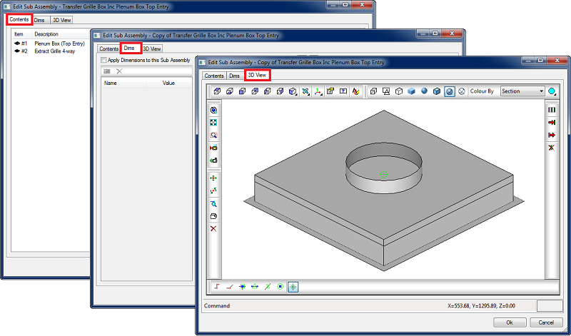
As illustrated above, the dialog is categorised into three individual tabs, these consist of : "Contents Tab", "Dims Tab" & "3D View Tab". For additional information and functionality, please refer to Sub-Assemblies - Toolbar/Commands documentation.
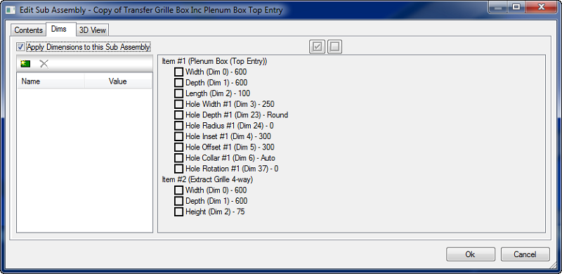
- The next stage is to customise and configure the critical dimensions to drive the combined items within the Sub assembly as a dynamic individual item. Select the "Dims" tab , then enable the "Apply Dimensions to this Sub Assembly option", the dimensions for each individual item will be indicated driving each pattern:
- Prior to setting up the critical dimensions. Plan and determine the dynamics required to drive the Sub assembly:
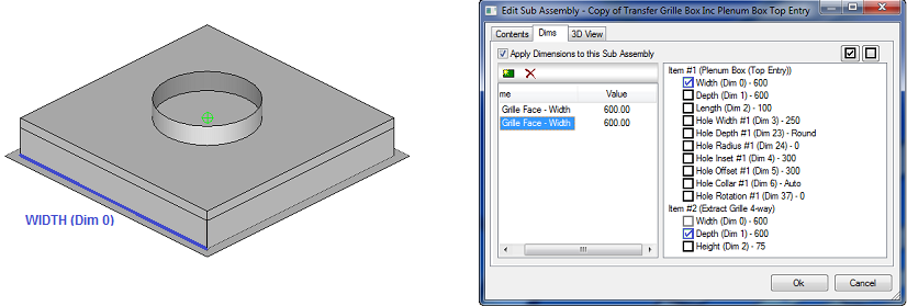
Dynamically driving the width of Item #1 (Plenum Box (Top Entry)) with Item #2 (Extract Grille 4-way)
Select "New Dimension" 
. The column below titled Name, will populate a "Dim#1" title, name as required "Grille Face - Width", then enter a value of 600.00 within the value column.
- To link the dimensions for "Width (Dim 0)" for "Item #1" & "Item #2", by selecting the box in each field, a tick will appear. This indicates the two items within the sub assembly are now being driven by one common dimension for width - (Dim 0) titled "Grille Face - Width".
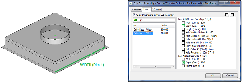
Dynamically driving the depth of Item #1 (Plenum Box (Top Entry)) with Item #2 (Extract Grille 4-way)
Select "New Dimension"
. The column below titled Name, will populate a "Dim#2" title, name as required "Grille Face - Width", then enter a value of 600.00 within the value column.
- To link the dimensions for width (Dim 1) for Item #1 & item #2, by selecting the box in each field, a tick will appear. This indicates the two items within the sub assembly are now being driven by one common dimension for width titled "Grille Face - Width".
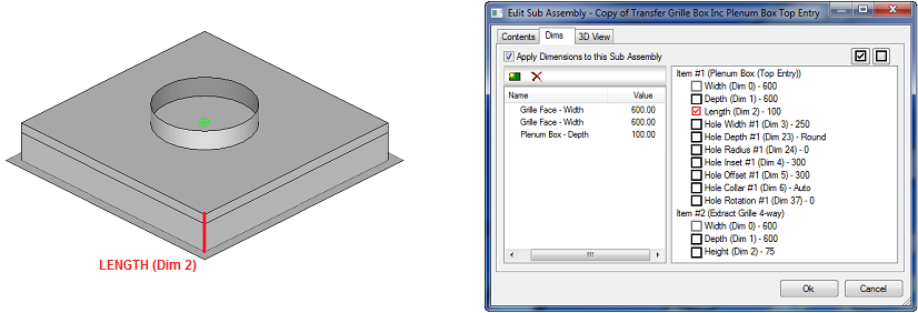
Driving the Length of Item #1 (Plenum Box (Top Entry)) independently from Item #2 (Extract Grille 4-way)
- Select "New Dimension"
. The column below titled Name, will populate a "Dim#3" title, name as required "Plenum Box Depth", then enter a value of 100.00 within the value column. - Select the dimension for Length (Dim 2) by selecting the box in the field, a tick will appear. This indicates item #1 can be independently drive the depth of the top entry plenum box.
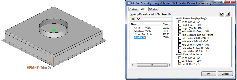
Driving the Length of Item #2 (Extract Grille 4-way)) independently from Item #1 (Plenum Box (Top Entry)
- Select "New Dimension"
. The column below titled Name, will populate a "Dim#4" title, name as required "Grille Depth", then enter a value of 75.00 within the value column. - Select the dimension for Length (Dim 2) by selecting the box in the field, a tick will appear. This indicates item #2 can be independently drive the depth of the grille.
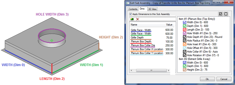
End Result - A fully configured Dynamic Sub Assemblies, were the user has the dynamic control of:
Grille Face Width : Item #1 (Plenum Box (Top entry)) & Item #2 (Extract Grille 4-way)
Grille Face Width : Item #1 (Plenum Box (Top entry)) & Item #2 (Extract Grille 4-way)
Grille Depth : Item #2 (Extract Grille 4-way)
Plenum Box Depth : Item #1 (Plenum Box (Top entry))
Collar X Location : Item #1 (Plenum Box (Top entry))
Collar Y Location : Item #1 (Plenum Box (Top entry))
- Default Insertion Point
A default insertion point is required on all items and sub assemblies. If this is not configured or applied correctly, the insertion of the item can become out of relationship with the cross hair / cursor. It is very important to plan the insertion location on how the item / sub assemblies will interact when utilising for design or co-ordination purposes within a building information model.
- To configure an insertion point appropriately on an item / sub assemblies, right click on the item, Select "Edit". Note: This can either be executed in the "Item folder" structure or alternatively within the "Service Template" if the item has been applied to the latter.
- The "Edit Sub Assembly" dialog will appear, Select the "3D View" tab:
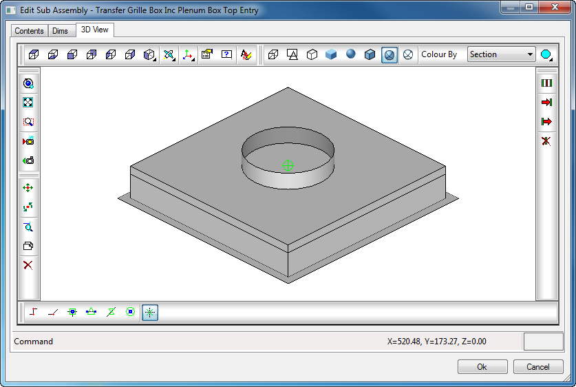
- When locating the required default insertion point, the basic principle to co-ordinate / move the item / sub assemblies, to be in a co-ordinate location (@ X=0 Y=0 Z=0). For this example "Transfer Grille Box Inc Plenum Box Top Entry" the default insertion can be located on the face node of the "Transfer Grille".
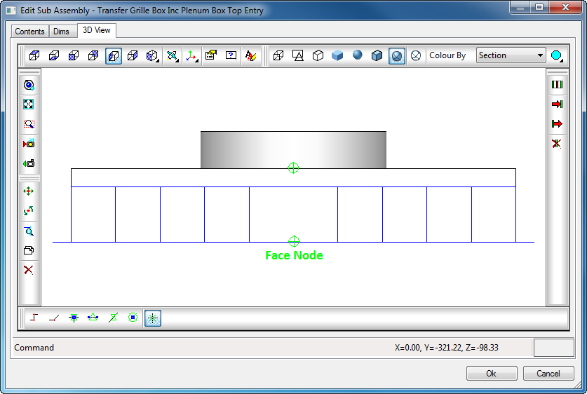
- Execute the Move command, Select the "Face Node" on the item / sub assemblies. Then type @0,0,0, this will move the selected, to the appropiate relative co-ordinate.
- To test the insertion of the item / sub assemblies, apply to the appropriate "Service Template" accordingly. Then apply within the model.