|
Access: |
Ribbon:
CAM tab
 Drilling panel
Drill
Drilling panel
Drill

|
A Drill operation provides access to a whole range of drilling, tapping and hole making operations. These include:
- Drilling - G81 style drilling with rapid out.
- Counterboring - G82 style drilling with dwell at bottom and rapid out.
- Chip breaking - Chip breaking with pecking and partial retracts between pecks.
- Deep drilling - Deep drilling with pecking and full retract between pecks.
- Guided deep drilling - gun drilling - Deep drilling that produces a very round hole with a precision diameter. Very useful for deep, straight holes in a variety of materials.
- Tapping - Tapping (G84/G74). Synchronous spindle speed and feed.
- Tapping with chip breaking - Tapping with chip breaking.
- Reaming - Reaming (G85 style) with feed out.
- Boring - Boring with dwell at bottom and feed out.
- Stop boring - Boring (G86 style) with spindle stop at the bottom and rapid out.
- Fine boring - Fine boring with shift away from the hole side.
- Back-boring - Boring from the back.
- Circular pocket milling - Circular pocket milling.
- Bore milling - Bore milling.
- Thread milling - Thread milling.
- Probe - Used to measure a feature on the part with a probe tool, or use macros from the machine to define the WCS. Needs special handling in the post processors depending on the machine.
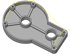
The input geometry for these cycles can be selected directly from the features of part geometry, and consistent with other 2D operations, input geometry can also be selected from a sketch, (for example: center points of arcs).
When working with solid models, the easiest way to use the drill feature is to select the cylindrical faces of the holes to drill directly. This automatically sets the correct stock height and depth for each hole, and allows having holes in different planes and different depths in a single drill feature. Observe also that when drilling from cylindrical faces, the Select same diameter option is available, and allows easy - and automatic - selection of many similar holes.
 Tool tab settings
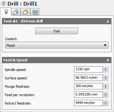
Coolant:
The type of coolant used with the tool.
Spindle speed:
The rotational speed of the spindle.
Surface speed:
The spindle speed expressed as the speed of the tool on the surface.
Plunge feedrate:
Feed used when plunging into stock.
Feed per revolution:
The plunge feedrate expressed as the feed per revolution.
Retract feedrate:
Feed used when retracting and not using rapid (G0) moves.
 Geometry tab settings
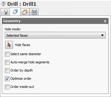
Select same diameter
Check this to automatically select all holes with the same diameter as the hole currently selected in the selection box.
Example: To drill a single 6 mm / 1/4" hole and all 12 mm / 1/2" holes, first select the 6 mm / 1/4" hole, then select one of the 12 mm / 1/2" holes, and then check the Select same diameter option.
Using this option is associative to the model. If additional holes with the same diameter are added later, regenerating the operation automatically includes the added holes in the drilling cycle.
Auto-merge hole segments
When drilling a hole with multiple segments, enable to have neighboring segments included automatically.
Order by depth
Specifies that the holes must be ordered by either increasing or decreasing Z-level.
Optimize order
Specifies that the holes should be ordered such that the machining distance is minimized.
Order inside-out
Enable to reorder holes from the default order to an order which machines inner holes first and then outer holes.
 Heights tab settings
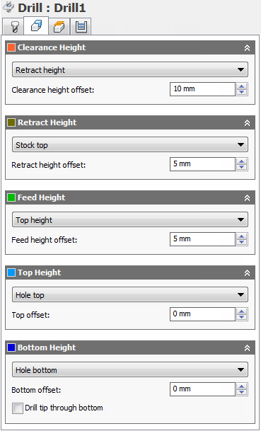
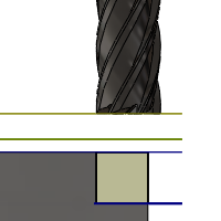
Clearance Height
The Clearance height is the first height the tool rapids to on its way to the start of the tool path.
Clearance Height
- Retract height: incremental offset from the Retract Height.
- Feed height: incremental offset from the Feed Height.
- Top height: incremental offset from the Top Height.
- Bottom height: incremental offset from the Bottom Height.
- Model top: incremental offset from the Model Top.
- Model bottom: incremental offset from the Model Bottom.
- Stock top: incremental offset from the Stock Top.
- Stock bottom: incremental offset from the Stock Bottom.
- Hole top: incremental offset from the Hole Top.
- Hole bottom: incremental offset from the Hole Bottom.
- Selection: incremental offset from a Point (vertex), Edge or Face selected on the model.
- Origin (absolute): absolute offset from the Origin that is defined in either the Setup or in Tool Orientation within the specific operation.
Clearance height offset:
The Clearance height offset is applied and is relative to the Clearance height mode selection in the above drop-down list.
Retract Height
Retract height mode sets the height that the tool moves up to before the next cutting pass. Retract height mode should be set above the Feed height and Top. Retract height mode is used together with the subsequent offset to establish the height.
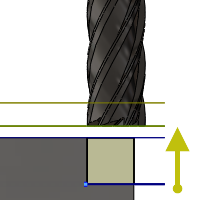
Retract Height
- Clearance height: incremental offset from the Clearance Height.
- Feed height: incremental offset from the Feed Height.
- Top height: incremental offset from the Top Height.
- Bottom height: incremental offset from the Bottom Height.
- Model top: incremental offset from the Model Top.
- Model bottom: incremental offset from the Model Bottom.
- Stock top: incremental offset from the Stock Top.
- Stock bottom: incremental offset from the Stock Bottom.
- Hole top: incremental offset from the Hole Top.
- Hole bottom: incremental offset from the Hole Bottom.
- Selection: incremental offset from a Point (vertex), Edge or Face selected on the model.
- Origin (absolute): absolute offset from the Origin that is defined in either the Setup or in Tool Orientation within the specific operation.
Retract height offset:
Retract height offset is applied and is relative to the Retract height mode selection in the above drop-down list.
Feed Height
Feed height mode sets the height that the tool rapids to before changing to the feed/plunge rate to enter the part. Feed height mode should be set above the Top. A drilling operation uses this height as the initial feed height and the retract peck height. Feed height mode is used together with the subsequent offset to establish the height.
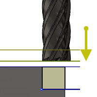
Feed Height
- Clearance height: incremental offset from the Clearance Height.
- Retract height: incremental offset from the Retract Height.
- Disabled: Disabling the Feed Height causes the tool to rapid down to the lead-in.
- Top height: incremental offset from the Top Height.
- Bottom height: incremental offset from the Bottom Height.
- Model top: incremental offset from the Model Top.
- Model bottom: incremental offset from the Model Bottom.
- Stock top: incremental offset from the Stock Top.
- Stock bottom: incremental offset from the Stock Bottom.
- Hole top: incremental offset from the Hole Top.
- Hole bottom: incremental offset from the Hole Bottom.
- Selection: incremental offset from a Point (vertex), Edge or Face selected on the model.
- Origin (absolute): absolute offset from the Origin that is defined in either the Setup or in Tool Orientation within the specific operation.
Feed height offset:
Feed height offset is applied and is relative to the Feed height mode selection in the above drop-down list.
Top Height
Top height mode sets the height that describes the top of the cut. Top height mode should be set above the Bottom. Top height mode is used together with the subsequent offset to establish the height.
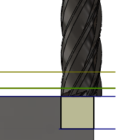
Top Height
- Clearance height: incremental offset from the Clearance Height.
- Retract height: incremental offset from the Retract Height.
- Feed height: incremental offset from the Feed Height.
- Bottom height: incremental offset from the Bottom Height.
- Model top: incremental offset from the Model Top.
- Model bottom: incremental offset from the Model Bottom.
- Stock top: incremental offset from the Stock Top.
- Stock bottom: incremental offset from the Stock Bottom.
- Hole top: incremental offset from the Hole Top.
- Hole bottom: incremental offset from the Hole Bottom.
- Selection: incremental offset from a Point (vertex), Edge or Face selected on the model.
- Origin (absolute): absolute offset from the Origin that is defined in either the Setup or in Tool Orientation within the specific operation.
Top offset:
Top offset is applied and is relative to the Top height mode selection in the above drop-down list.
Bottom Height
Bottom height mode determines the final machining height/depth and the lowest depth that the tool descends into the stock. Bottom height mode needs to be set below the Top. Bottom height mode is used together with the subsequent offset to establish the height.
Bottom Height
- Clearance height: incremental offset from the Clearance Height.
- Retract height: incremental offset from the Retract Height.
- Feed height: incremental offset from the Feed Height.
- Top height: incremental offset from the Top Height.
- Model top: incremental offset from the Model Top.
- Model bottom: incremental offset from the Model Bottom.
- Stock top: incremental offset from the Stock Top.
- Stock bottom: incremental offset from the Stock Bottom.
- Hole top: incremental offset from the Hole Top.
- Hole bottom: incremental offset from the Hole Bottom.
- Selection: incremental offset from a Point (vertex), Edge or Face selected on the model.
- Origin (absolute): absolute offset from the Origin that is defined in either the Setup or in Tool Orientation within the specific operation.
- To chamfer width: allows the tool to drill just enough to make the chamfer width match the input parameter. The input parameter should not exceed the tool's chamfer width. The calculated height offset is dependent on the tool's parameters (diameter, tip diameter, and tip angle) and on the diameter of the hole. Acceptable selections include cylindrical faces, circles, or arcs.
- To chamfer diameter: the diameter of the new hole is equal to the input parameter. Therefore, the input parameter should not exceed the tool's diameter. The calculated height offset is dependent on the tool's parameters and independent of the hole selection. Acceptable selections include cylindrical faces, circles, or arcs.
Bottom offset:
Bottom offset is applied and is relative to the Bottom height mode selection in the above drop-down list.
Drill tip through bottom
Enable to make the tool tip drill completely through the bottom.
Break-through depth:
Specifies how far the tool drills past the bottom of the hole to ensure through-cutting.
 Cycle tab settings
Cycle type:
The Cycle type is the type of drilling cycle. Inventor HSM Express provides a number of predefined (canned) drilling cycles.
Selecting a drill cycle determines which parameters can be specified for the drilling operation.
-
Drilling - rapid out
Regular drilling recommended for drilling holes with depths of less than three times the tool diameter.
-
Counterboring - dwell and rapid out
Enlarges one end of a previously drilled hole; the enlarged end normally ends in a flat interior. A dwell is used to improve the finish of a hole.
-
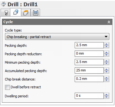
Chip breaking - partial retract
Drills holes with depths of more than three or four times the tool diameter by periodically retracting the tool to clear chips and/or flood the hole with coolant. This is also known as Peck drilling.
-
Deep drilling - full retract
Drills holes with depths of more than three or four times the tool diameter by periodically retracting the tool out of the hole to clear chips and/or flood the hole with coolant. This is also known as Peck drilling.
-
Guided deep drilling - gun drilling
A standard gun drill has a single effective cutting edge. This unique head geometry is different from a conventional twist drill. While drilling, guide pads burnish the hole allowing the hole to maintain straightness. The result of this activity is a very round hole with a precision diameter that can also produce deep, straight holes in a variety of materials.
-
Tapping
Taps right or left internal threads in a round hole with a multi-point tool.
-
Left tapping
A tap that rotates counterclockwise as it enters the hole to cut a thread.
-
Right tapping
A tap that rotates clockwise as it enters the hole to cut a thread.
- Tapping with chip breaking
- Reaming - feed out
- Boring - dwell and feed out
- Stop boring - stop and rapid out
- Fine boring - shift
- Back-boring
- Circular pocket milling
- Bore milling
- Thread milling
-
Probe
Used to measure a feature on the part with a probe tool, or use macros from the machine to define the WCS. Needs special handling in the post processors depending on the machine.
Pecking depth:
Sets the depth for the first peck move, which plunges in and out of the material to clear and break chips.
Pecking depth reduction:
The amount by which the pecking depth is reduced per peck.
Minimum pecking depth:
The minimum allowed pecking depth.
Accumulated pecking depth:
Specifies the pecking depth which forces full retract.
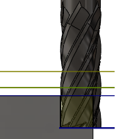
Chip break distance:
With a chip breaking operation, the drill withdraws a specified distance after advancing into the hole to prevent the binding of chips.
Dwell before retract
Enables dwelling before pecking retracts to thin out chips. This can increase tool lift significantly depending on the material being machined.
Dwelling period:
The Dwelling period is the dwelling time in seconds. Specifying a dwell time halts all axis movement for a specified time while the spindle continues revolving at the specified rpm. This can be used to ensure that chips are cleared before retracting from a hole, and will typically improve the finish of a hole.
Typically a dwelling time between 1/4 second and 1 second is sufficient. As an example, specify 0.25 or 1/4 in this field to dwell for 1/4 second.
When post processing a drill cycle, the dwell time is specified as one of the drill cycle parameters (typically P), and in most cases it is output in milliseconds (ms).
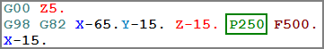
250ms dwell time in G82
When posting using expanded cycles, the dwell time is output as a regular dwell command (G4).
To calculate the minimum dwell time that will ensure at least one complete revolution, use a value of 60 divided by the spindle speed. As an example, at 350 RPM the minimum dwell time should be 60 / 350 = 0.171s (which could be rounded to 0.2s).