Use the 2D Contour strategy with a chamfer mill to machine the chamfer along the outside edge.
- On the ribbon, click
CAM tab
 2D Milling panel
2D Contour
2D Milling panel
2D Contour
 .
.
 Tool tab
- On the Tool tab, click the
 button to open the Tool Library dialog box.
 - From the Sample Libraries > Tutorial library, select tool #50 - Ø10 mm 45° chamfer.
- Click
 to close the Tool Library dialog.
 Geometry tab
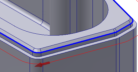
Since the chamfer already exists as a model feature, there are two edges from which to choose for the geometry - one at the top of the chamfer and one at the bottom. Inventor HSM allows either to be used, but in most cases choosing the bottom edge allows for the easiest setting of parameters. However, in both cases Inventor HSM automatically calculates the correct horizontal offset, and only the additional vertical tip offset needs to be specified
- Click the Geometry tab and select the edge at the bottom of the chamfer as the contour selection.
 Passes tab
When a chamfer mill is selected as the tool, the Chamfer option is automatically enabled and displays the Chamfer width and Chamfer tip offset chamfering parameters.
Since an edge on the actual chamfer feature in the model was selected, it is not necessary to set the Chamfer width. But to ensure that the tool tip is not coincident with the lower edge of the chamfer, the Chamfer tip offset must be specified.
- Click the Passes tab.
- Set the Chamfer tip offset: to: 0.25 mm
Start the Calculation
- Click
 at the bottom of the Operation dialog box, or right-click in the graphics window and select OK from the marking menu, to automatically start calculating the toolpath.
The toolpath should appear as shown in the following image:
This completes the toolpaths for this part. You can now simulate and post process the result.
Continue to To Post Process the Toolpaths...