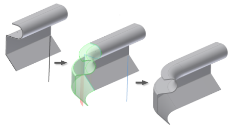
You can create a contour roll as a regular or a base feature.

- Create or share a sketch consisting of lines, arcs, splines, and elliptical arcs (as required) within your model.
or
For a base feature, create a profile sketch consisting of lines, arcs, splines, and elliptical arcs (as required). Include a line to represent the axis of rotation in your sketch or ensure that your sketch is positioned to use one of the default axes as the rotation axis
Note: Like the Contour Flange feature, the Contour Roll feature transforms sharp sketch corners into bends in the finished part using the bend radius value. - Exit sketch.
- On the Sheet Metal tab, Create panel, click Contour Roll. The Contour Roll dialog box displays.
- Click the profile geometry to revolve.
- In the Contour Roll dialog box, click the axis selection command.
- Click the axis of rotation. Note: Rotation axis geometry must be contained within the sketch containing the profile geometry.
- If necessary, change the direction of the material offset from the profile curve.
- If necessary, change the Rolled Angle value or direction. Note: You can use a Rolled Angle value of 360 degrees only for profiles with a single, straight line. The angle value cannot equal 360 degrees for multi-segment profiles.
- Optionally, select an alternative Unroll Method. Note: Alternative Unroll Methods can require additional graphical selections or value entries.
- Optionally, select an alternative Unfold Rule.
- Optionally, enter an alternative Bend Radius value.
- Click OK to create the Contour Roll and close the dialog box.