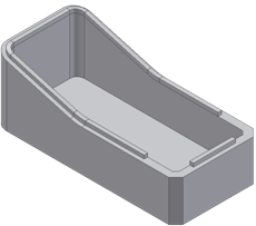
Limit the lip extension on one of the paths to two trimming planes.
- Create or import a thin-walled part like the one in the following image. Note: The open face is tangent continuous.
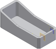
- Define two work planes and two work points (see the red circles) along the path.
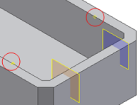
- On the ribbon, click 3D Model tab
 Show Panel icon
  . Select Plastic Part panel to display the Plastic Part panel, and then select Lip
  .
. - Select the two paths (shown in blue and red in the picture). Note: Do not select the chamfer edges; leave the path open.
- Select the Z axis as the Pull direction.
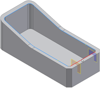
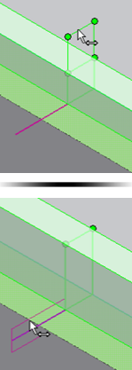
- Use the manipulators on the preview to adjust the Lip cross section and the clearance volume. You can drag the cross section to a more convenient location along the path.
- Expand the Path Extents selector, and select the two planes and the two points. At first, the Lip algorithm makes a tentative choice of sectors. Use the green and yellow dots to choose which sections to keep or remove.
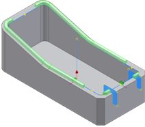
- Click the green or yellow dots until the configuration is like the one in the picture.
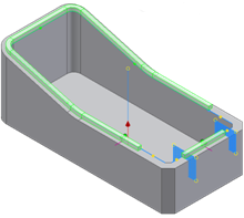
- Click OK.
