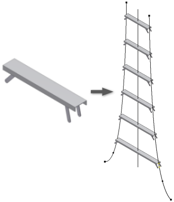
Many designs require the creation of subassemblies which contain similar geometry, only the size or position in the main assembly is slightly different. The manual creation and positioning of these subassemblies is time consuming. The iCopy command automates the process of copying and positioning similar components in the main assembly. iCopy combines skeletal modeling and adaptivity to allow the subassembly to change shape to fit its position in the model. This workflow is beneficial for curtain wall panels, rungs on a ladder, frames, or any subassembly where the size varies based on the position in the main assembly.
There are four steps to the iCopy process:
iCopy Terms
The following terms are used in this section to define iCopy and the related components.
- iCopy template
- An assembly file that is authored for use with the iCopy command. This file contains the iCopy definition information, the adaptive skeleton part, and the geometry that defines the model.
- iCopy template layout part
- The adaptive part file that drives the other skeleton geometry. This part is selected in the iCopy Author. This part is derived into other components in the assembly to build the skeleton model.
- iCopy definition
- Information entered in the iCopy Author dialog box. An iCopy Definition node is added to the browser when an assembly is authored.
- iCopy result
- Assembly files created by the iCopy command. These assembly files are copies of the iCopy template that are place and adapted in the target assembly.
- Target assembly
- The assembly where the iCopy results are placed. This assembly must contain at least one part which is used to position the iCopy results.
- Target layout part
- The part in the target assembly that is used to position the iCopy results and define the pattern of results.
- Create the target assembly, including the target layout part containing geometry/patterns for placing/adapting copied assemblies.
- Create a skeleton assembly, including the template layout part containing sketch geometry, and parts derived from the skeleton template layout/shape.
- Use the iCopy Author command in the assembly to enable it as an iCopy template. This results in an iCopy template containing the iCopy definition.
- Use the iCopy command to create one or more iCopy results. Each iCopy result contains the iCopy definition, so any iCopy result can be used as an iCopy template.
Target Assembly
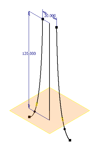
The target assembly is the destination for the iCopy results. This assembly contains the target layout part. The target layout part contains the geometric representation that determines the shape for each assembly copy built by the iCopy command.
Skeleton Assembly
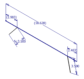
The skeleton assembly is the file that is used with the iCopy Author to create the iCopy template. This file is created using skeleton modeling techniques. The skeleton assembly contains a layout part that drives the other components in the assembly. Creating the assembly requires:
- Set the iCopy template layout part to adaptive. The layout part drives the geometry of the other components in the assembly. Setting the layout part as adaptive allows the iCopy command to change the layout part based on its position in the target assembly. The adaptive nature of this assembly allows each iCopy result to have a unique shape. Note: Fully constrained sketch geometry can cause problems with adaptivity. For best results, do not fully constrain sketch geometry.
- Create and test the template layout part. Test the layout part by placing the skeleton assembly in a test assembly. Use adaptivity to change the skeleton model and verify that it updates as expected.
- Create each additional part for the iCopy template by deriving the part from the layout part. Creating parts derived from a layout part is the basis of skeletal modeling. The shape/sketch geometry is derived from the layout into other part documents. The derived geometry forms the basis for solid geometry and additional detail in the child parts.
- Insert additional parts into the skeleton assembly. The skeleton assembly can contain derived parts that change shape and static parts that are referenced by each iCopy result.
Constrain the skeleton assembly in a particular way for best results with adaptivity.
- Constrain the iCopy template layout part origin to the iCopy template assembly origin. Use a flush constraint to constrain each of the origin planes (XY/XY, YZ/YZ, and XZ/XZ).
- Constrain the origin of each part derived from the layout part to the iCopy template layout part origin. Use a flush constraint to constrain each of the origin planes (XY/XY, YZ/YZ, and XZ/XZ).
- Constrain any part that does not derive its position from the layout to other parts in the template assembly. Other parts in the template assembly can include the layout, other derived parts, and other non-derived parts.
iCopy Author
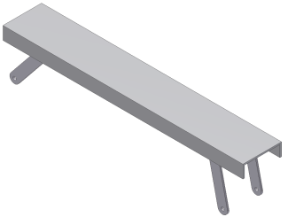
The iCopy Author command creates an iCopy template from an adaptive skeleton assembly. When authoring the iCopy template, you select points to position and size the component geometry. You select the parameters to make available in the iCopy command, and attach drawings or presentation files to copy for each iCopy result.
The iCopy Author command prepares the following required data in the skeleton layout part (within the adaptive skeletal assembly) for use by the iCopy command:
- Sketch geometry points (the endpoints of lines, arcs, and circle center points, but not sketch points)
- (Optional) Parameters used to vary the iCopy results
- (Optional) Drawings (.idw, .dwg) or presentation files (.ipn)
iCopy Placement
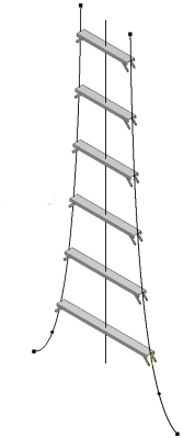
The iCopy command creates one or multiple copies of the iCopy template and adds each copy to the target assembly. Each assembly (iCopy result) can vary from other iCopy results in the pattern depending on the adaptivity that was used in the iCopy template. During the iCopy command, parts can be set to copy or reuse depending on the definition and purpose.
Drawing (.idw, .dwg) or presentation (.ipn) files can be attached to the iCopy template using the iCopy Author. The drawing or presentation files are copied during the iCopy operation. The references for each drawing or presentation file are changed to point to the iCopy results.
To place a single iCopy result requires work points to position/size the iCopy result. These work points correspond the points selected in the iCopy Author.
To create a pattern of iCopy results requires:
- Work plane that is patterned; used as frame of reference / intersection for patterning the work points.
- Path for work plane pattern.
- Offset / number of copies / flip direction for work plane pattern.
- Rail (geometry) to guide the patterning of each work point (input).
To associate a pattern of iCopy results to an existing feature pattern requires:
- Pattern of work points for each point in the iCopy template
- Number of copies / flip direction for iCopy pattern