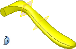
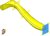
For an open loft, select a point for the beginning or end section, and then apply conditions to the point section.


To create a loft with a pointed or cone-shaped tip, apply the Sharp point condition. To create a loft with a rounded, dome-shaped tip, apply a tangent condition. To control the rounded tip, apply a tangent to plane condition and select a tangency plane.
Lofts between two-point sections must include an interior section to define the section shape.
- On the ribbon, click 3D Model tab
 Create panel
  Loft
Loft  .
. - On the Curves tab, specify the sections to loft. Click under Sections, and then click the sections in the sequence you want the shapes to blend.
- Point sections must be at the beginning or end of the loft.
- If you select multiple sections on any plane, they must intersect.
- If more than one loop is in a sketch, first select the sketch, and then select the curve or loop.
- Optionally, specify whether to create a loft with rails, or a centerline. Use the context menu and switch between Sections, Rails, and Centerlines, or change the selection type in the dialog box. Select a single 2D or 3D curve for centerline, or one or more curves for guide rails. Sections must intersect rails, but need not intersect a centerline. Note: When specifying a centerline with a point, the centerline must pass through the point section and near the middle of the neighboring section.
- If the part contains more than one solid body, to choose the participating body, click the Solids selector.
- In Output, select solid, or surface.
- To join the beginning and ending sections of the loft, click Closed Loop.
- To merge loft faces without a seam, click Merge Tangent Faces.
- Under Operation, click Join, Cut, Intersect or new solid .
- On the Conditions tab, specify the boundary condition for the listed sections and rails.
For point sections:
- Sharp Point Creates a pointed or cone-shaped tip.
- Tangent Creates a rounded, dome-shaped tip. Then set the weight of the condition.
- Tangent to Plane Select, specify a work plane or planar face, and then set the weight of the condition.
For other sections and rails:
- Free Condition Applies no boundary condition.
- Tangent Condition Creates a loft tangent to the adjacent faces. Then set the weight of the condition.
- Direction Condition Specifies that the angle is relative to the section or rail plane. Set the angle and the weight of the condition.
- Smooth (G2) Condition Creates a loft curvature continuous to the adjacent faces.
Note: The sketch or edge that you select highlights in the graphic. - On the Transition tab, Automatic Mapping is selected by default. If appropriate to modify automatically created point sets, or to add or delete points, clear the checkbox.
- To modify, add, or delete, click the point set row.
- A default calculated map point is created for each section sketch. To specify a unitless value (zero represents one end of the line; one represents the other end. Decimal values represent positions between ends), click position.
Note: The point set or map point that you select highlights in the graphics area. - To create the loft, click OK.
 Show Me How to create a loft to a point