On the ribbon, click Place Views tab  Create panel
  Section to create a full, half, offset, or aligned section view from a specified parent view. A section view is automatically aligned to its parent view.
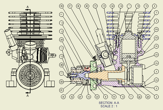
In the following image, a section view was used to expose components for ballooning.
Tip: Select Section View Preview as Uncut, in the Drawing tab in Application Options, to display the preview of the section view as uncut. This option controls the display of the preview of the model, and when enabled, increases the performance of the previews of section views.
You can define the view cutting line while Section View is active or create sketch geometry to use for the view cutting line.
To change the depth of a section view, right-click the section view or cutting line, select Edit Section Properties from the menu, and then change the setting in the dialog box.
When creating section views of presentations with trails, the trail is visible in the drawing view. If appropriate, right-click a view or a single trail and select Show Trails to turn trails on or off.
When you either sketch a multi-segment section line or select a view sketch containing a multi-segment section line, you can specify the method of the section view, projected or aligned.
Tip: To place the view without alignment to the parent view, press Ctrl as you move and place the preview.
Create a section view
|
|
- On the ribbon, click Place Views tab
 Create panel Create panel  Section . Section .
- Select an existing view to use as the parent view.
- Click to set the start point for the view cutting line, and then click to place additional points for the line. The number and location of points on the view cutting line determine the type of section view.
- Right-click, and then select Continue to complete the view cutting line.
- In the dialog box, edit the view identifier and select the scale. Click Toggle Label Visibility to change the label visibility. Click Edit View Label to edit the view label in the Format Text dialog box.
- Set the display style.
- Set the section depth for the view.
- Select the method of the section view, projected or aligned, if possible.
- Move the preview to the appropriate location, and then click to place the view. You can place the view only within the alignment indicated by the view cutting line.
|
Create a section view defined by sketch geometry
Create aligned section views
When you either sketch a multi-segment section line or select a view sketch containing a multi-segment section line, you can specify the method of the section view, projected or aligned.
If one or more segment angle is non-perpendicular, the default method is set to Aligned. If all segment angles are exactly 90 degrees, the default method is set to Projected.
| |
- Select an existing view to use as the parent view.
- On the ribbon, click Place Views tab
 Sketch panel Sketch panel  Create Sketch to open a drawing sketch associated to the view. Create Sketch to open a drawing sketch associated to the view.
- Create sketch geometry to define a view cutting line, and then close the sketch.
- On the ribbon, click Place Views tab
 Create panel Create panel  Section . Section .
- Select the view cutting line you defined in the sketch.
- In the dialog box, set the label, scale, display style, and section depth for the view. If you do not change these settings, the default settings are assigned.
- In the Method area, set the preferred projected method.
- Move the preview to the appropriate location and click to place the view. You can place the view only within the alignment indicated by the view cutting line.
To change the projected method, select the section view, right-click and select
Edit Section Properties. Tip: You can use an unconsumed model sketch as a section line.
|
Create a slice operation with a section view
| |
- On the ribbon, click Place Views tab
 Create panel Create panel  Section . Section .
- Select an existing view to use as the parent view.
- Click to set the start point for the view cutting line, and then click to place additional points for the line. The number and location of points on the view cutting line determine the type of section view.
- Right-click, and then select Continue to complete the view cutting line.
- In the dialog box, set the label, scale, display style, and section depth for the view. If you do not change these settings, the default settings are assigned.
- Move the preview to the appropriate location, and then click to place the view. You can place the view only within the alignment indicated by the view cutting line.
|
Note: (Cut Inheritance):
- Isometric projected views created for section views inherit the section cut by default.
- Orthographic projected and auxiliary views support the inheritance of the section, but it is switched off by default.
- To switch on or off the inheritance of the section cut, right-click the child view, and select Edit View. Open the Display Options tab of the Drawing View dialog box, and select the Section option in Cut Inheritance.
 Create panel
  Section to create a full, half, offset, or aligned section view from a specified parent view. A section view is automatically aligned to its parent view.
