- On the ribbon, click Sketch tab
 Create Panel Line , or right-click and select Line from the marking menu.
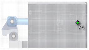
 - In the graphics window, move your cursor into the center of the construction circle previously projected. When the green dot appears, indicating that you have located the center of the projected circle, click to place the first point of a line segment:
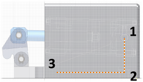
- Paying attention to the vertical and horizontal constraint indicators, place a vertical and a horizontal construction line segment by selecting two additional points. Your profile should appear as follows:
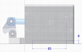
- Click Sketch tab Constrain panel Dimension or right-click and select Create Dimension from the marking menu Then, place a horizontal length dimension of 85 mm that defines the distance between the guard mounting holes.
- Continue by placing a vertical dimension of 8 mm between the bottom edge of the guard and the horizontal construction line:
- click Sketch tab Show Panel icon
 . Select Format panel to display the Format panel. Then select Construction to reset your geometry creation to normal geometry.
 - Click Sketch tab Create Panel Point .
- Place three sketch points at the ends of the two construction line segments.
- Click Sketch tab Exit panel Finish Sketch , or right-click and select Finish 2D Sketch to exit the sketch environment.
Note: You can optionally continue to work with a hidden edge display. The remaining illustrations in this tutorial show a shaded display. To return to a shaded display, click View tab Appearance panel Shaded from the drop-down menu under Visual Style.
Appearance panel Shaded from the drop-down menu under Visual Style. 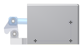
Now that you have sketched Center Points, you will next place two different-sized Punch features to provide clearance for the pin and holes for mounting screws.