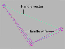
IK solvers are the mathematical algorithms behind the IK handles. IK solvers calculate the rotations of all the joints in a joint chain controlled by an IK handle. The effect an IK handle has on a joint chain depends on the type of IK solver used by the IK handle. By default, Maya loads the following IK solvers on start-up:
- Single-Chain IK solver (ikSCsolver)
See Single Chain solver and Create a single chain IK handle.
- Rotate-Plane IK solver (ikRPsolver)
See Rotate Plane solver and Create a rotate plane IK handle.
- Human IK solver (hikSolver)
The human IK solver is only used by characters that have been characterized. You cannot use the hikSolver with regular IK handles.
If you want to pose and animate joint chains that have between two and four joints, use single chain or rotate plane IK.
By default, each IK handle you create that uses the same type of IK solver, also shares the same IK solver node. For example, all IK handles that use single chain IK also connect to the same ikSCsolver node. Consequently, if you edit the attributes of the shared IK solver node, all the IK handles that connect to the node are affected. If you want to fine-tune the IK solvers for certain IK handles only, while not affecting other IK handles, you can create additional IK solvers for your IK handles using the createNode MEL command.
IK solver calculations
When you move an IK handle, the solver performs the appropriate calculations to move and rotate all the joints in its IK chain accordingly. First, the solver looks at the position (Translate X, Y, and Z attributes) and orientation (Rotate X, Y, and Z attributes) of the IK handle. Next, the solver calculates how to move the position and orientation of the end effector as close to the IK handle’s position and orientation as possible. To do that, the solver calculates how to best rotate the joints in the IK handle’s joint chain. Finally, the solver then rotates all the joints in the joint chain so that the end effector reaches the IK handle’s position and orientation.
Single Chain solver

A single chain IK handle uses the single chain solver to calculate the rotations of all the joints in the IK chain. Also, the overall orientation of the joint chain is calculated directly by the single chain solver.
Difference between single chain and rotate plane IK handles
The difference between a single chain IK handle and a rotate plane IK handle is that the single chain IK handle’s end effector tries to reach the position and the orientation of its IK handle, whereas the rotate plane IK handle’s end effector only tries to reach the position of its IK handle. Since the rotate plane IK handle’s end effector only tries to reach the position of its handle, the resulting joint rotations are more predictable. For the rotate plane IK handle, the orientation of its entire joint chain is controlled by the twist disc manipulator. For more information, see Twist disc and Rotate Plane solver.
If your joint chain suffers from flipping, use the rotate plane solver instead of the single chain solver. The rotate plane solver was introduced with the pole vector to control the flipping of IK chains that you sometimes get with the single chain solver.
Rotate Plane solver


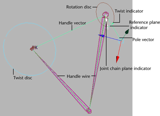
A rotate plane IK handle uses the rotate plane solver to calculate the rotations of all the joints in its IK chain, but not the joint chain’s overall orientation. Instead, the IK rotate plane handle gives you direct control over the joint chain’s orientation via the pole vector and twist disc, rather than having the orientation calculated by the IK solver. The single chain solver and rotate plane solver differ in this respect. See Difference between single chain and rotate plane IK handles.
The rotate plane solver is ideal for posing joint chains (such as arms and legs) that you want to stay in the same plane. For example, the shoulder, elbow, and wrist joints of an arm driven by a rotate plane IK handle all stay within the same plane as the elbow rotates. The plane itself can be rotated from the shoulder joint by the pole vector.
See also Pole vector.
Rotate Plane IK handle components
- Twist disc
-
The twist disc is a manipulator that you can use to twist or rotate the joint chain. The twist disc is located at the end joint of the IK chain.
Translating the pole vector often leaves the IK chain pointing in the wrong direction. You can use the twist disc to re-orient the plane after you move the pole vector to prevent flipping. To view an image of the twist disc, see Rotate Plane solver.
- Joint chain plane
-
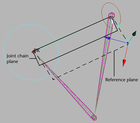
The joint chain plane is the plane that contains all the joints in the joint chain and poses through the axis. The joint chain plane rotates about the handle vector. When you manipulate the pole vector, you are rotating the joint chain plane about the handle vector. To view an image of the joint chain plane, see Rotate Plane solver.
- Reference plane
-
For the joint chain plane to rotate and twist the joint chain, the plane must rotate relative to some other plane so that the degree of twist can be measured. The plane that the joint chain plane rotates relative to is the reference plane. To view an image of the reference plane, see Rotate Plane solver.
- Pole vector
-
The pole vector is a manipulator that lets you change the orientation of the IK chain. The pole vector also lets you control flipping.
Since moving the pole vector changes the orientation of the reference plane, moving the pole vector can also change the orientation of the joint chain directly; just as manipulating the twist disc can change the orientation of the joint chain. This is because the joint chain’s degree of orientation—or twist—is defined as the difference in orientation between the reference plane and the joint chain plane. To view an image of the pole vector, see Rotate Plane solver.
Danger:When positioning your IK handle, if the handle vector and the pole vector cross each other or point in exact opposite directions, the joint chain can suddenly flip. You can prevent this flipping by moving the pole vector so that the handle vector does not cross it or point in the opposite direction from it.
Rotation disc
The rotation disc is an indicator that displays how much the IK chain has been rotated by the twist disc. The rotation disc is located at the start joint of the IK chain. To view an image of the rotation disc, see Rotate Plane solver.
- Reference plane indicator
-
The reference plane indicator is the green dot on the rotation disc that moves to reflect the movements of the pole vector.
- Twist indicator
-
The twist indicator is the green arc between the reference plane indicator and the joint chain plane indicator on the rotation disc. The twist indicator displays the orientation of the joint chain relative to the reference plane.
- Joint chain plane indicator
-
The joint chain plane indicator displays the orientation of the joint chain plane relative to the reference plane. The joint chain plane indicator appears in the rotation disc.