A Custom Code node allows you to write a custom function and add it to a shader.
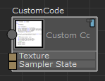
To create a Custom Code node,  -click and select Tools > Toggle Advanced Mode to enter advanced mode, then select Hw Shader Nodes > Various > Custom Code. By default, the Custom Code node contains two inputs: Texture and Sampler State. The square port for each of these inputs signifies that it can accept more than one input. This node allows you to read pixels from textures. By default, there are no outputs for the node.
 In Extension for Maya LT 2015, select Settings > Toggle Advanced Mode from the ShaderFX menu bar to enable advanced mode.
Press Edit in the Attribute Editor to enter your code in the Custom Code editor that appears. A basic editor is provided, but you can also write your code in any editor and then copy and paste into this one when your code is complete. A struct and a basic function definition are provided for you to begin.
The first struct denotes the output; by default, it is float4 color.
struct CustomCode1188Output
{
	float4 color;
};
The function definition defines the input parameter; by default, it is float inputA.
CustomCode1188Output CustomCode1188Func( float inputA )
The Custom Code Attribute Editor lists the Function Name: for example CustomCode1188.

You can customize the Function Name; however, your struct, function, and Function Name must all be identical.
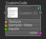
After you close the editor, the inputA input and color output are created.
Shader languages
Different shader languages are used, depending on the rendering engine and platform.
- SFX_HLSL_5: for DirectX 11 mode
- SFX_CGFX_3: for OpenGL mode
- SFX_GLSL_4: for OpenGL on Windows
- SFX_GLSL_1_2: for OpenGL on Mac OS X
- SFX_HLSL_5: for DirectX 11
- SFX_SWATCH: for rendering a swatch inside ShaderFX (but value is false when rendering inside Viewport 2.0)
- SFX_HLSL_3: can be exported
- _3DSMAX_: for use in 3ds Max
- _MAYA_: value is true if shader is running inside Maya
If you plan to use both DirectX and OpenGL modes, ensure that your functions include languages for both of these modes. Also ensure that you have included languages for each of the operating systems.
Examples
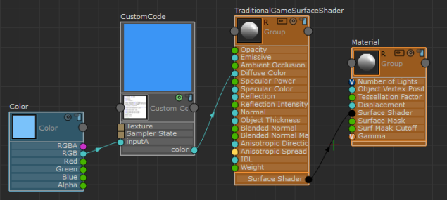
In this simple example, the output is the input color multiplied by itself. The Custom Code swatch shows a darker blue than the blue connected via inputA.
struct CustomCode1181Output
{
    float3 color;
};

CustomCode1181Output CustomCode1181Func( float3 inputA )
{
    CustomCode1181Output OUT;
    OUT.color = float3(inputA*inputA);
    return OUT;
}
The following example demonstrates how to sample the texture in a few of the languages that Maya supports, then multiply the sampled values by the input color. The if/endif and ifdef/endif statements wrap code with an if statement that is executed at compile time.
struct CustomCode1178Output
{
    float3 color;
};

CustomCode1178Output CustomCode1178Func( float3 inputA, float2 UV )
{
    CustomCode1178Output OUT;

    float3 t = float3(0,0,0);
    #if defined(SFX_CGFX_3) || defined(SFX_HLSL_3)
        t = tex2D( SFX_SAMPLER0, float2(UV.x, 1-UV.y) ).xyz;
    #endif

    #ifdef SFX_HLSL_5
        #if defined(SFX_SWATCH) || defined(_3DSMAX_)
            t = SFX_TEXTURE0.Sample( SFX_SAMPLER0, UV );
        #else
            t = SFX_TEXTURE0.Sample( SFX_SAMPLER0, float2(UV.x, 1-UV.y) );
        #endif
    #endif

    #ifdef SFX_GLSL_4
        t = texture( SFX_TEXTURE0, float2(UV.x, 1-UV.y) ).xyz;
    #endif

    #ifdef SFX_GLSL_1_2
        t = texture2D( SFX_TEXTURE0, float2(UV.x, 1-UV.y) ).xyz;
    #endif

OUT.color = inputA * t;

return OUT;
}
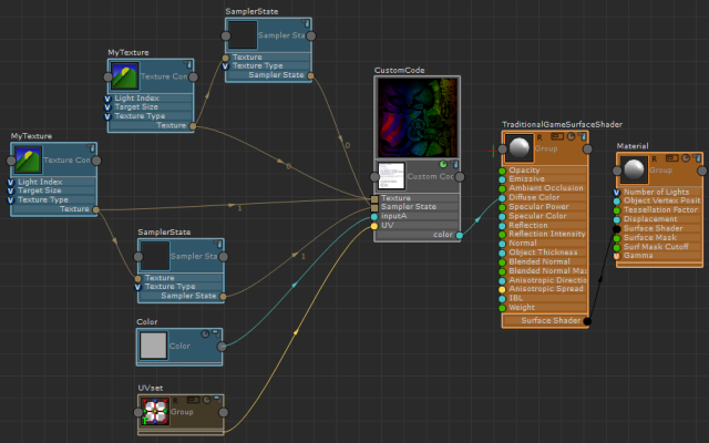
After creating your Custom Code node, create the following nodes and connect them as indicated in the graph below:
- Hw Shader Nodes > Textures > Texture Component
- Hw Shader Nodes > Textures > Sampler State
- Hw Shader Nodes > Values > Color
- Hw Shader Nodes > Inputs Common > UV Set
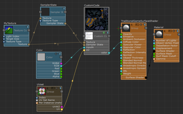
Now, when you use DirectX 11, the texture in Viewport 2.0 and in the swatches are sampled using the SFX_HLSL_5 code. When you use OpenGL, the texture in Viewport 2.0 is sampled using the SFX_CGFX_3 code while the swatches are sampled using the SFX_GLSL_4 code (for Windows).
The comments in the Custom Code editor also advise you to use SFX_TEXTURE[n] or SFX_SAMPLER[n] to refer to your textures. This way, you do not have to hardcode the texture names (for example, grass_texture_A). SFX_TEXTURE[n] and SFX_SAMPLER[n] refer to the order in which you connect your textures. The first Texture Component/Sampler State node pair you connect are SFX_TEXTURE[0] and SFX_SAMPLER[0], respectively, and the next pair are SFX_TEXTURE[1] and SFX_SAMPLER[1], respectively. In the graph above, you can see that the connections emitting from the Texture Component and Sampler State nodes also indicate 0.
The following is an example graph with two Texture Component/Sampler State pairs. One pair has connections that indicate 0, and the other pair has connections that indicate 1. You may also want to group the nodes for better organization.
