Sweeps out a surface by revolving a profile curve around a pivot point.
Related topics
NURBS > Revolve > 
- Axis Preset
-
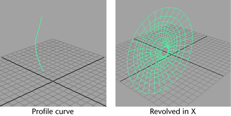
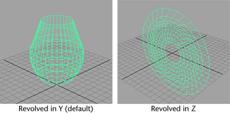
Specifies the revolution axis. The default is Y. In the following figure, a profile curve (drawn in the front view) is revolved using each revolution axis in the perspective view.
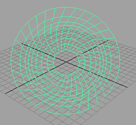
If you set the Axis Preset to Free, you can enter values in the Axis X, Y, or Z boxes to specify the axes about which the profile curve is revolved. The following figure shows a surface resulting from a value of 1 for Axis X, Y, and Z .
- Pivot
-
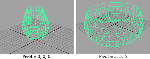
If you set Pivot to Object, the revolve is performed from the default pivot location (0, 0, 0). This is the default.
If you select Preset, you can change the X, Y, or Z location of the pivot point by entering values in the Pivot Point boxes.
The following figure shows how a revolved surface is created with default pivot values and with values of 5 for X, Y, and Z.
- Surface Degree
-
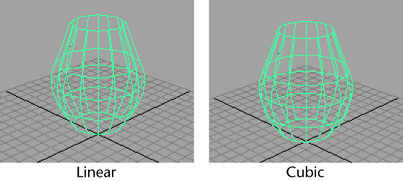
The Surface Degree options determine whether the V parameter direction of the surface is created with linear (degree 1) or cubic (degree 3) geometry.
If you select Linear, the surface is constructed with flat facets all around.
If you select Cubic, the smooth profiles are defined by the original profile curve. This is the default.
- Start and End Sweep Angle
-
Use the Start Sweep Angle and End Sweep Angle values to specify the angle of revolution in degrees. The default is 360, with a valid range of 0 to 360.
- Use Tolerance
-
The Use Tolerance options control the accuracy of the resulting revolved surface. You can apply tolerance globally or locally.
If you select None you can change the segments value.
If you select Global tolerance, Maya uses the Positional and Tangential values in the Settings part of the Preferences window.
If you select Local tolerance, you can directly enter a new value that overrides the Positional tolerance of the Preferences window. This lets you create the revolved surface closer to the actual surface of revolution.
- Segments
-
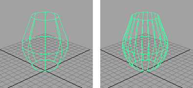
The Segments value determines how many sections are used to create the surface of revolution. With a sweep of 360 degrees, six or eight sections are usually sufficient. In the following figure, the left surface shows the revolve with eight segments. The right shows 20 segments.
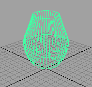
If Use Tolerance is not set to None, the Segments value is automatically computed so that the result differs from the default revolved surface by less than the specified tolerance value.
If Local is set as the Use Tolerance option, the tolerance value of the revolved surface is closer to the actual surface of revolution.
 Tip:
Tip:If animating the sweep angle, change the Segments value instead of the tolerance value to change the numbers of CVs of the surface.
- Curve Range
-
Select Complete as the Curve Range to create the revolved surface along the entire profile curve. This is the default.
Select Partial if you want to use a segment of the curve for the revolve.
If you set the Curve Range to Partial before you create the revolved surface, a subCurve is created. By lessening the length of the subCurve, you lessen the length of the revolved surface.
To edit the length of the subCurve, select the revolved surface, select the subCurve in the Channel Box, select the Show Manipulator Tool, then drag the curve segment manipulator or edit the Min and Max Value in the Channel Box.
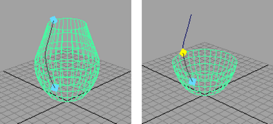
For more details on editing subCurve, see Editing the subCurve attributes.
- Output Geometry
-
Specifies the type of geometry created. (Subdiv means subdivision surfaces.)
- Input Curve
-
The Input Curve information is read-only. It gives you access to the history of the curve you used to create the revolved surface.
Editing the subCurve attributes
If you set the Curve Range to Partial in the options window when the revolve was created, you can edit the length of the curve. Select the revolved surface, then use the Show Manipulator tool or Channel Box to edit the subCurve attributes.