For injection molded parts, the part is constrained in the mold. During the solidification of an injection molded part, shrinkage of the solidified layer is prevented by two mechanisms. Once the part is ejected from the mold, these residual stresses will be released in the form of shrinkage deformation
There are two mechanisms preventing shrinkage of the solidified layer while still in the mold. Firstly, adhesion to the mold walls restrain (at least the outer skin of) the solid layers from moving, and secondly, the newly formed solid surface will be kept fixed by the stretching forces of melt pressure.
In-cavity residual stresses build up during solidification. Due to the nature of constrained quenching, the residual stresses distribution is largely determined by the varying pressure history, coupled with the frozen layer growth. Once the part is ejected from the mold, these residual stresses will be released in the form of shrinkage deformation. If the initial strains, which are equivalent to the in-cavity residual stresses, are uniform, the part will shrink uniformly without any warpage and post-mold residual stresses. Warpage is caused by variations in shrinkage throughout the part.
Two types of shrinkage variations are considered:
- Shrinkage variations from region to region (differential shrinkage effects)
- For typical thin-walled parts, this form of shrinkage variation can be divided into variations in the thickness direction of molded parts, mainly caused by the differential cooling and variations from surface region to surface region.
- Shrinkage variation in different directions (orientation effect)
- The difference between parallel and perpendicular shrinkage, and anisotropic material properties relating to the fiber-orientation distribution are one of the main causes of part warpage for fiber-filled thermoplastics.
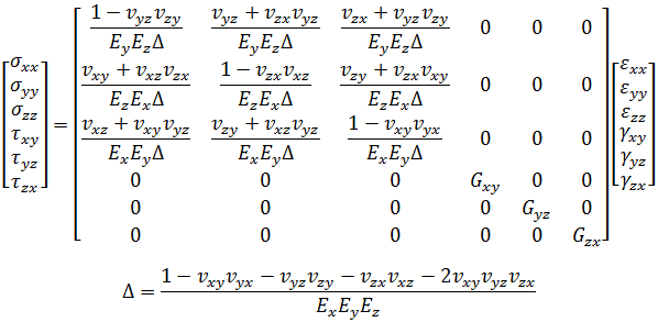
The shrinkage of injection molded parts depends on the thermodynamic behavior of the material during processing. For simplicity, we assume linear elastic behavior in the solidified part and purely viscous behavior in the melt.
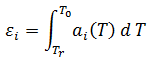
where
-
 is the linear thermal expansion coefficient (CTE) at temperature T in the i-th principal direction.
 - T0 is the temperature when the local cavity pressure reached the atmospheric condition. This value is obtained from the flow simulation.
- Tr is the room temperature.
The 4-node first-order tetrahedral element is appropriate for 3D flow simulation. However, if the first-order tetrahedral element is used for the Warp analysis of typical thin-walled parts or thin-walled areas of complex three-dimensional parts, the notorious shear locking problem will make the structural response very stiff [1]. Shear locking, or parasitic shear, is caused by an inaccuracy in the linear displacement field of a linear tetrahedral element. It can be exacerbated by elements with large aspect ratios. On the other hand, the high aspect ratio tetrahedral elements may not be avoidable if the computational cost is to be kept low. Therefore, the first-order tetrahedral element is not suitable for the thin-walled areas of injection molded parts.
A hybrid element scheme has been designed for the 3D Warp analysis. 4-node first-order tetrahedral elements are used in the 3D solid areas, and 10-node second-order tetrahedral elements are used in the thin-walled areas. Transitional 5-9 node tetrahedral elements are used in the transitional areas which connect the thin-walled and thick areas.
3D warpage simulation normally requires significant computational time particularly if the number of elements is very large and if there is a big thin-walled region. An efficient preconditioned conjugate gradient iterative solver is implemented for reducing the memory requirement and computational time.
References:
[1] K.J. Bathe, Finite Element Procedures, Prentice Hall Inc.(1996).
[2] S.G.Advani and C.L.Tucker III, The Use of Tensors to Describe and Predict Fiber Orientation in Short Fiber Composites, J. Rheol., 31,751-784(1987).
[3] G.P.Tandon and G.J.Weng, The Effect of Aspect Ratio of Inclusions on the Elastic Properties of Unidirectional Aligned Composites, Polym. Compos. 5(4),327-333(1984).
[4] R.A.Schapery, Thermal Expansion Coefficients of Composite Materials Based on Energy Principles. J. Compos. Mater., 2, No.3, 380-404, (1968).