You can select one or more of the following results:
- Principal residual stress (first principal and second principal stresses).
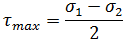
- Maximum shear stress.
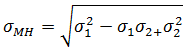
- Mises-Hencky stress.
The mathematical derivation of these results can be illustrated with the aid of the well known Mohr's circle which depicts the stress state at a point.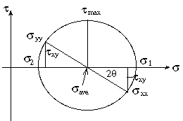
First principal and second principal stress
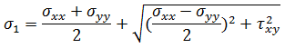
 is the maximum normal stress and
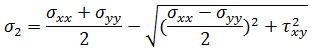
  is the minimum normal stress. The corresponding directions of the principal stresses are called the first principal and second principal direction respectively. The angle for these is calculated using the following equation:
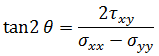
Maximum shear stress
Mises-Hencky stress
Interpreting the stress results
In general, when examining stress results, check the distribution of stresses within the part and the maximum stress levels in the part.Stress and Warp outputs results for both the top and bottom of the element (Normalized thickness = 1 and -1 respectively).
These need to be compared against recommended maximum stresses for the material and any relevant design criteria for the part, for example, specified failure criteria.
Non-filled, isotropic materials will in general exhibit either brittle or ductile behavior, as illustrated in the following figure, where (a) represents brittle and (b) ductile stress-strain behavior.
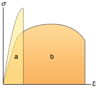
The recommended stress results to consider in each case are:
- For brittle materials, consider the principal stress results.
- For ductile materials, consider the Mises-Hencky result.
For fiber-filled, anisotropic materials, the behavior of the part under load, the mechanics of failure, and the design criteria for failure will be considerably more complex than for an isotropic material. Stress analysis of composite materials, and interpretation of the results obtained, requires special expertise on the part of the user.
Both the fiber orientation and Stress/Warp analyses output results on a per-laminate basis through the thickness of the part.