Inserts are modeled with flat shell surfaces representing each of the faces on the insert. The complete insert is effectively a closed volume defined by the top bottom and side surfaces. Inserts can have complex cross sections to match features on the cavity model. Inserts can also be joined to one another to create more complex shapes.
Modeling requirements
Do not apply a thickness values to the insert surface(s).
Inserts must not contact the mold outer surfaces. When a small insert butts onto a larger insert, the surface of the larger insert must have an internal boundary where the smaller insert contacts it.
When the edge of a plastic surface runs across an insert surface, the insert surface should have an internal boundary added to ensure that the mesh on the plastic surface and the mesh on the insert surface are compatible.
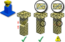
Where an insert projects from a feature such as a boss on the plastic part, the insert surfaces should either have internal boundaries coincident with the open edge of the boss or the insert should be modeled as two inserts stacked end to end, with the junction occurring at the height of the end of the boss. This will ensure that the mesh on the insert surface is compatible with that on the coincident plastic surface. This modeling requirement is illustrated in the following figure.