In this task, you will use the two mesh fixing tools, Merge Nodes and Swap Edge, to eliminate high aspect ratio elements.
Aspect ratio: Swap Edge
- Ensure the Tutorial 3 project you created in Task 1 is open.
- Click
 .
. - Navigate to the Tutorial folder, typically C:\Users\Public\Public Documents\Autodesk\Simulation Moldflow Synergy 20xx\tutorial.
- In the Files of type drop-down list, select Study files(*.sdy).
- Click on the file
tutorial_3_task_4.sdy
and click Open.
The connectivity issues from the previous task have been corrected on this model. We are going to isolate elements with a defined range of aspect ratios and place them onto a diagnostic layer.
- Click
 () to open the Mesh tab.
 - Click
 () to display the Aspect Ratio Diagnostic pane.
 - Enter a Minimum aspect ratio value of 8, and a Maximum aspect ratio value of 15.
- Select Place results in diagnostics layer to move elements with aspect ratios within the above range to their own layer.
- Click Show, and then click Close.
- In the Layers panel, right-click the layer with the name
Diagnostic results
and select Hide All Other Layers.
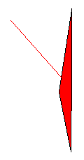
The high aspect ratio elements are highlighted with projecting spikes. You may need to rotate the model slightly to see the spikes.
- Click
 ().
(). - Using the ViewCube, click
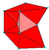
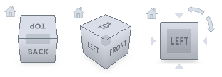 Back View. It appears that there are two adjacent elements displayed. Rotate the model slightly and it becomes apparent that one element is in front of the other. Zoom and rotate the model until you see the element as shown below, with its spike projecting towards you.
- To see how to deal with a high aspect ratio element, it is helpful to see the adjacent elements. In the Layers pane, click
 Expand Layer.
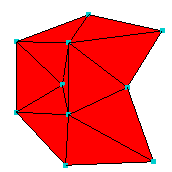
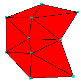
The Expand Layer dialog appears. Leave the default Expand current selection by "1" level(s).
- Click OK.
The display should now be similar to the following:
- Click
 .
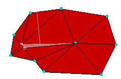
. - Click the element with the high aspect ratio, which has the spike protruding from it.
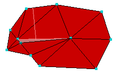
The element number will appear in the Select first triangle box of the Swap Edge tool pane. - Click the element attached to the long edge of the high aspect ratio element:
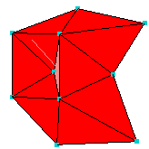
The second element's number will appear in the Select second triangle box of the Swap Edge tool pane. - Click Apply.
The high aspect ratio element has been eliminated by altering the nodes that are joined to form the local surface.
- Click Close on the Tools pane.
Note: Alternatively, click
 , click and drag the node to a more suitable position.
 - Click then click
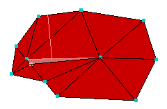
 Previous. Rotate and zoom in on the model so that you can select the element as shown below.
Previously we swapped edges to resolve the high aspet ratio element. In this instance, we would replace a high aspect ratio element that runs across the screen with one that runs up the screen. We need a different approach, which is to merge nodes.
- Click
 .
.
The Merge Nodes pane appears.
- Click on one of the nodes along the short edge of the high aspect ratio element. This first node is the target of the merge.
- Click on the other node along the short edge of the element. This is the node that will be merged onto the target node.
The sequence of node selection will alter the resultant merge. Autodesk Simulation Moldflow Insight has filled in the node identification numbers in the Input Parameter boxes of the Merge Nodes pane.
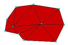
- Click Apply.
The second node is merged into the first node, and the surrounding elements are adjusted accordingly.
- Close the Merge Nodes dialog.
The above methods can be used to eliminate, one by one, the remaining high aspect ratio elements in the mesh.
In the next task, you will learn how to fix free edges.
Click the Next topic link below to move on to the next task of the tutorial.